At the recent Everything Open Conference, I attended a taik by Vic OIiver on the one handed keyboard called the Quirkey.
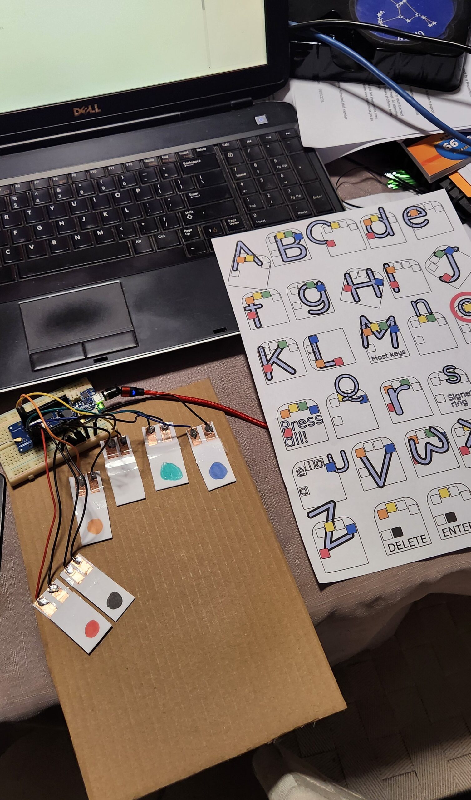
I am attempting to write this blog post using a version of this keyboard I have made out of cardboard, a Arduino MKR 1310 board and some other bits and pieces of stuff that I found lying around the house. (I am going to have to stop here and go back to my regular QWERTY keyboard. I will have another practice later, but at the moment I am finding that I am using the ‘backspace’ more than I would like to.)
While looking into the Arduino code, it occured to me that I had a dev board that would actually work with this code (the Arduino MKR 1310 which had been used in a previous project). In particular, this board supported the HID, and Keyboard and Mouse libraries, which is what allowed this board to appear as (surprise, surprise) a keyboard and mouse device when plugged into a USB port. There ae many naferious project ideas for this sort of technology, but I don’t think that the usefulness has been explored enough.
The Design
This project code takes the corded (multiple symaltanious keypress) inputs, of six buttons, and converts it into regular keyboard input. Vik’s presentation gives more of the backgound, and reasons why knowing how to use one handed keyboard is a good skill to have. In addition, the documentation includes helpful tools to assist in learning this skill, as will as a typing tutor.
So… I have an Arduno board that will do the job (there is a good list of supported boards on the HID Library page), I just need to get some switches.
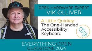
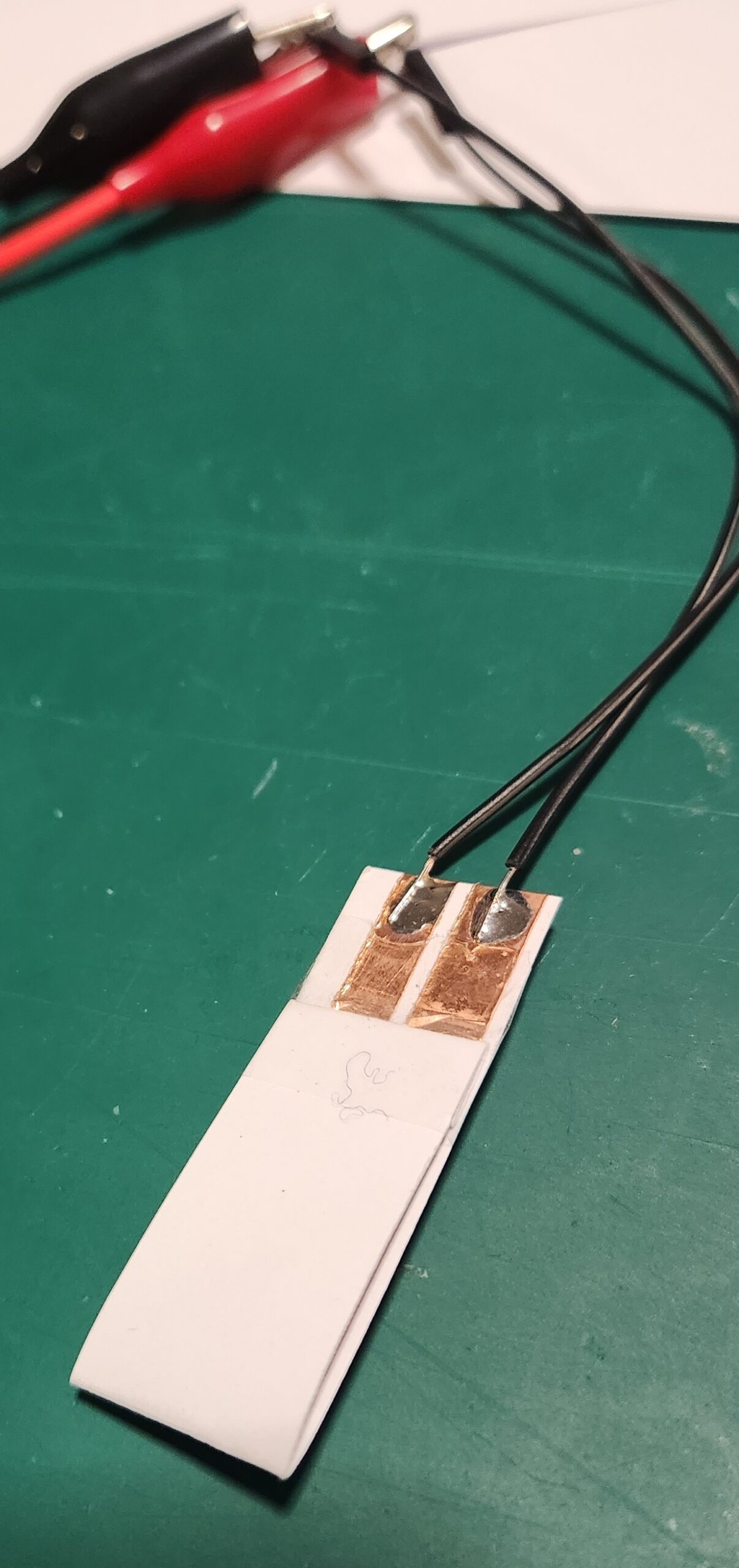
The latest version of the Quirkey keyboards were the result of lots of trial and erro experimentation, and consited of a 3D printed shell with six mechancal switches. My Prusa printer is currently broken and I didn’t have any unused mechanical switches within reach, but I did have some cardboard, copper tape and my trusty soldering iron. So, after some of my own experimentation, we get the following design…
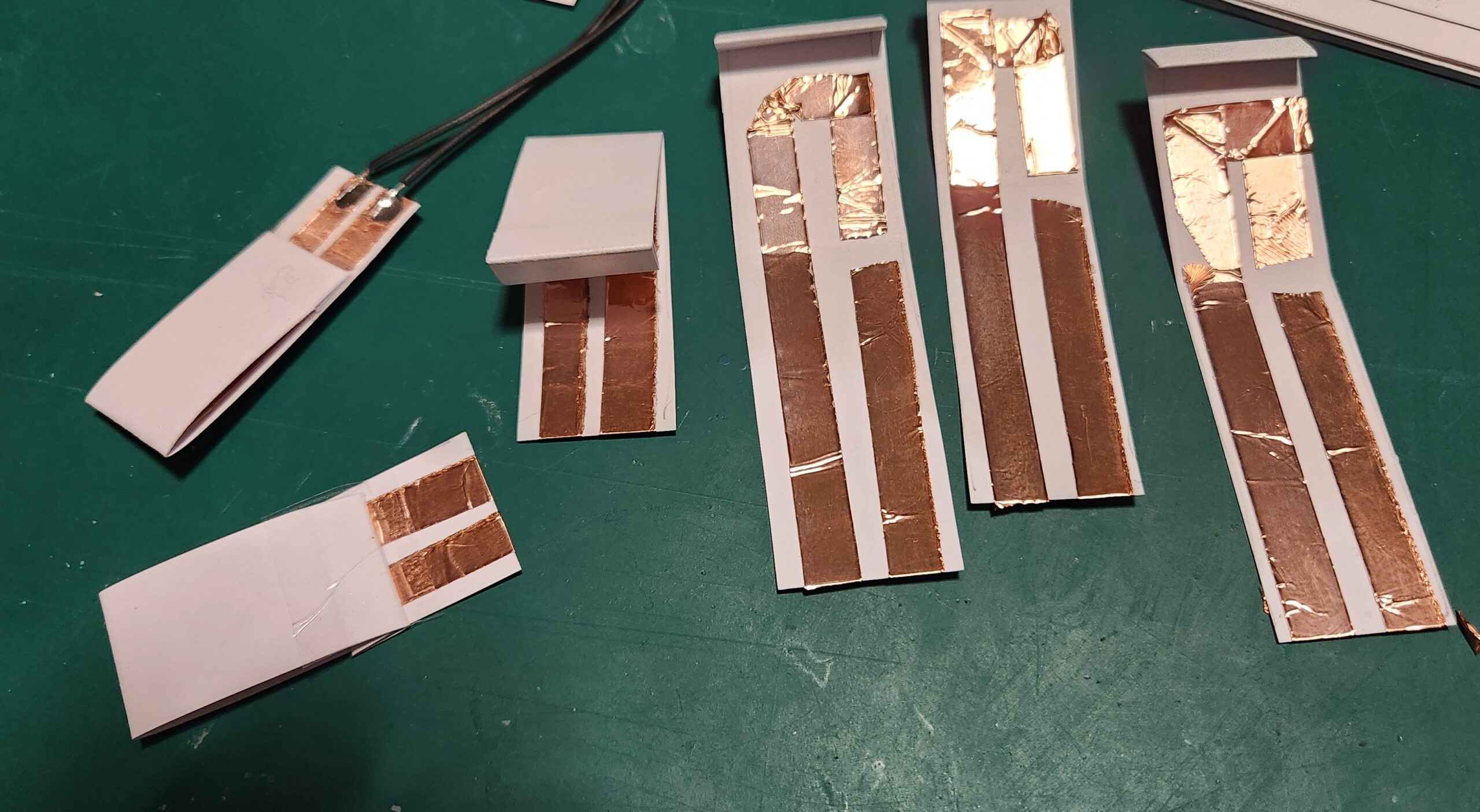
The cardboard switches are stuck down onto a piece of cardboard, wired up to the Arduino MKR 1310 board (any MKR 1000 series boar will work), and programmed with the MicroWriter Ardunio sketch. (Comments in the sketch indicate which pins connect to which switch.)
There is a 5 second delay on startup, but the board is now detected as an “Arduino LLC Arduino MKR WAN 1310 Keyboard” and “Arduino LLC Arduino MKR WAN 1310 Mouse”, and works as advertsed.
Conclusion
This is a great cheap-n-cheerful project incorporating a bunch of useful ‘maker’ techniques (soldering, wiring and Ardunio programming) which can be completed resonably quckly.. and at the end you get something useful to play with.
The switches aren’t perfect, but it’s great to have something to use to learn the one handed keyboard technique.
After practicing for a while, for not much more, the paper and copper switches and cardboard can be replaced with something a little more permanent. (A project for the future.)
This article is part 1.5 of the series – Developing a component for ESPHome, for the SX1262 LoRa Radio Chip. The process getting the LoRaWAN functionality of this development board to work with The Things Network proved to be an excercise infrustration management, so the following is a write up of what was required to get it to work. The following is my account of setting up the Heltec Wireless Lite V3 for connecting to the LoRaWAN network. There were several false starts, but in the end it was possible to send data and decode it correctly.
Development Environment
ArduinoIDE and the Heltec Board Manager extention
The Heltec boards are defined by the following file (link) which is added through the menu in Preferences…->Additional boards manager URLs
This file specifies that esptool 3.3.0 is used for writing the firmware to the Heltec board. There is as issue with usung this version for the Heltec V3 boards, in that the firmware compiles and installs, but puts the ESP32-S3 processor into a boot loop.
Install the ‘SX126X-Arduino’ library with the library manager (currently version 2.4.0).
A small fix is required. Edit the ‘src/mac/Commissioning.h’ file and comment out the check for whether the LoRaWAN Region has already being set (Line 40).
Example Code – LoRaWAN.ino
From the LoRaWAN library, the LoRaWAN example was copied and modified to get the system to work.
Modifications:
Copy the LoRaWAN.ino file, and remove other unnecessary files. Fix the source to remove the dependancies.
Simplify the code. eg. Remove the code sections used for other processors.
Set the authentication mode to OTAA, the device type and the Frequency bandplan region to AU915 by adding the optional parameters to ‘lmh_init() – true, CLASS_A and LORAMAC_REGION_AU915.
Ensure that the correct LoRaWAN sub-band is being used for AU915 by calling ‘lmh_setSubBandChannels(2)’.
Additional Serial.println() output added to trace the execution of the firmware, including the output of the LoRaWAN parameters.
The LoRaWAN parameters (AppEUI, DevEUI and AppKey) are set in the following section.
The Things Network
The Heltec V3 Devices have not been configured as known devices in The Things Network, and need to be specifically setup.
Select “Enter end device specifics manually”.
Add a new device and set the following Device Parameters
Frequency Plan: Australia 915-928 MHz, FSB 2 (used by TTN)
LoRaWAN Version: LoRaWAN Specification 1.0.2
Regional Parameters version: RP001 Regional Parameters 1.0.2 revision B
Create a JoinEUI (previously known as the AppEUI). This can be freely set any 8-byte value, but cannot be changed once set.
The other parameters that need to be set are:
DevEUI
AppKey
The easiest way to to get these values is to allow them to be automatically generated by The Things Network interface. They can be specifically set if the manufacturer of a device has preprogrammed a device with a LoRaWAN configuration.
Build and Install Firmware on Device
Update the definitions of the LoRaWAN parameters in the code to reflect the values just generated. It is possible to directly produce the desired strings (in ‘msb’ format) from The Things Network device interface.
It is also helpful to also have these values displayed when the board os booted.
The firmware compiles and can be installed onto the Heltec board. On boot, it should connect to the LoRaWAN network and start transmitting packets of data.
Uplink Payload Formatter
On The Things Network, to check that the uploaded data is correct, the following JavaScript payload filter can be installed for the device, which will decode the data and (hopefully) display the correct string.
function decodeUplink(input) {
var result;
result = String.fromCharCode.apply(null, input.bytes);
return {
  data: {
    bytes: input.bytes,
    result: result
  },
  warnings: [],
  errors: []
};
}
Notes, Issues and Errors
When selecting and playing around with different LoRaWAN Versions and Regonal Parameters, it appears as though The Things Network does not reset LoRaWAN values properly. Changing the LoRaWAN version to 1.1.0 required the additional parameter ‘NwsKey’. If the LoRaWAN version is then set back to 1.0.2, this value becomes the one that is used for the AppKey. There is a note about this in The Things Network interface, but it is not obvious what is required.
Care needs to be taken when setting the nodeDevEUI and nodeAppEUI not to set them the wrong way around. If connection packets are being received from the device, but it isn’t able to authenticate, then the nodeDevEUI will be correct, but the other parameters (including LoRaWAN Version) may be wrong.
If only intermittent transmitted packets are seen in The Things Network, and the device is not able to authenticate, check that the firmware has selected and is using the correct LoRaWAN sub-band.
Selecting other LoRaWAN versions eg. 1.1.0 will require additional parameters to be set., namely NwsKey. This setting is not removed if the LoRaWAN version is set back to 1.0.2, and this value is then used instead of the nodeAppKey. This is a trap. The only way to fix this is to delete the device definition in The Things Network and start over.
Next Steps
Convert the Arduino LoRaWAN firmware to ESPHome. This will allow LoRaWAN to be able to be used with the other ESPHome functions, including support for all of the existing supported sensors and outputs, and also operate with Home Assistant. (This will be Part 2 of the “Developing a component for ESPHome, for the SX1262 LoRa Radio Chip” series.)
Test with the Helium network. Register the device on the Helium network and check that data is routed correctly.
Implement as Class B and Class C LoRaWAN device. The example code currently only uploads data. Class B and Class C deviced allow data to be downloaded as well, for device control.
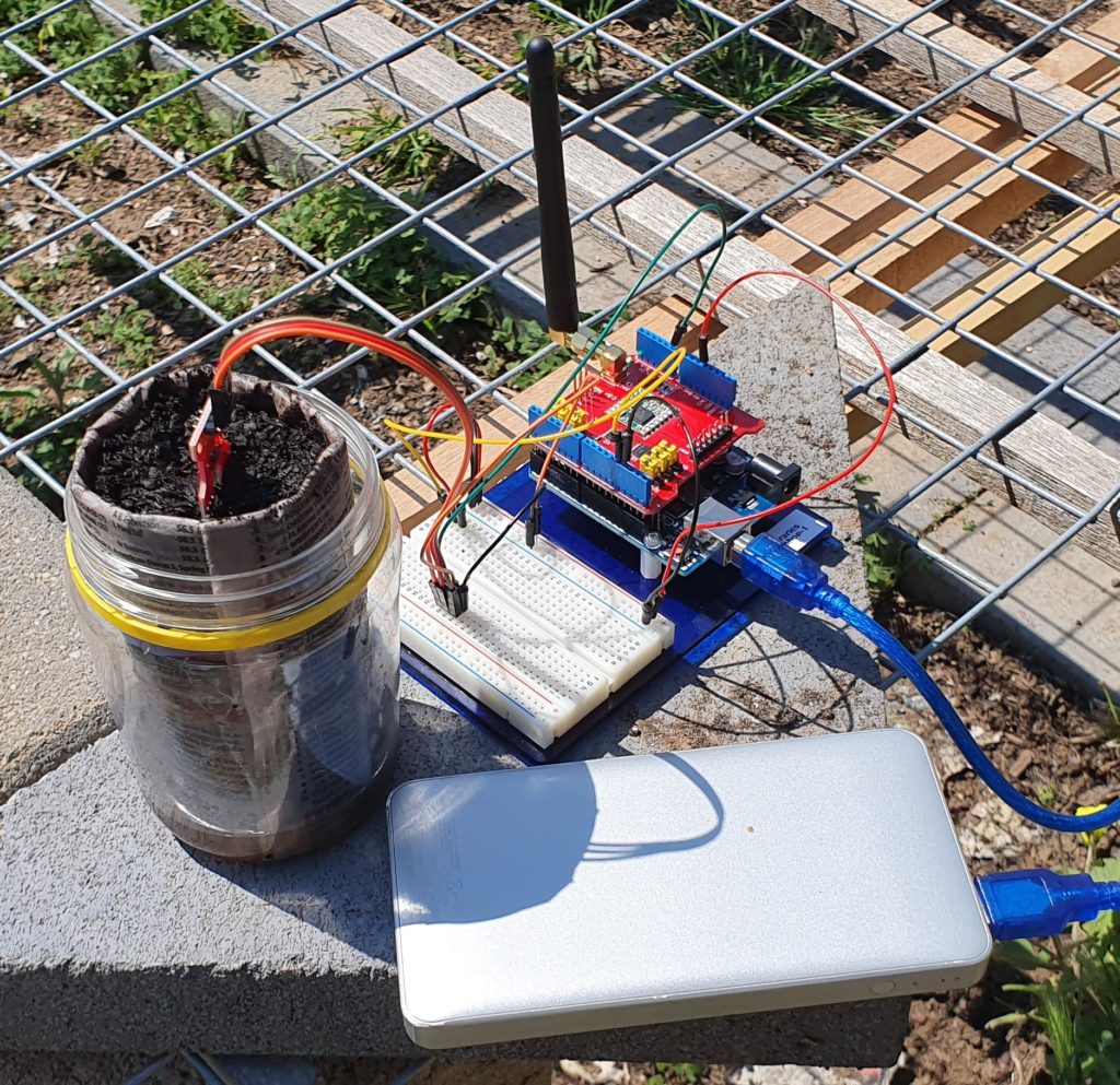
Open Energy Monitor is a project based in Wales which has developed an energy and environmental monitoring system. They have an energy sensor (the emontx series) which monitors the current in up to four(4) channels, together with the AC voltage, in order to measure the power flowing through electrical circuits.
Current transformers are used, and are placed by clamping around individual wires, allowing the current in the wire to be measured without making any change or direct contact to the existing wiring.
The Open Energy Monitor store are selling their sensors as a kit, and one has been ordered with four current transformers. This will be paired with an already available Arduino UNO to allow for an evaluation of the monitoring software.
We are just after the power measurements for each channel to be reported via a serial connection rather than using their project specific radio (a 433MHz radio link).
All of the code that they are using (with and without the radio link) is available via their forum and github repository.
As we evaluate this system we will be posting the results here.
The Open Energy Monitor also has a good set of documentation on how the units work, how they have been put together, and more on the theory of energy monitoring using current transformers.
In the third session, we are taking the data and looking at how it can be processed, in this case using the NodeRed tool.
Installation of Node-RED
Node-RED is a web server program which uses Node.js, which can be installed on a home computer, server, Raspberry Pi or in the Cloud. It can be used to collect and process the data collected by The Things Network[1].) We will be using MQTT to get access sensor data.
For supported Operating Systems and installation instructions, see: https://nodered.org/docs/getting-started/
On Linux Operating Systems (Ubuntu, Debian, Endebian etc.), Node-RED can be installed with
It also appears to be installable on Windows 10 using the Windows Subsystem for Linux (WSL)[2].
Once installed, ot can be accessed via web browser connecting to port 1880. If it is installed on the local computer, ot can be accessed by visiting the URL – http://localhost:1880/
A User Guide with Tutorials are available from the Node-RED website[3]. If you have access to a working Node-RED server then the Tutorials are a good way to get started.
One final note. Flows are stored on the computer under the computers name (hostname). It that is ever changed, then the flows will not be loaded and it will look like your configuration has dissapeared. It is still there, and will reappear if the hostname is changed back. The easiest way to fix this is to export your flows to a file first (json) and then import them afterwards. This option is under the main menu.
Once Node-RED has been installed it can be accessed via port 1880.
Some additional packages are required. These are installed via the Manage Palette menu.
node-red-contrib-persist
node-red-dashboard
Configuration is done by connecting processing nodes with virtual wires to create flows. This allows messages to be processed as they pass through the system.
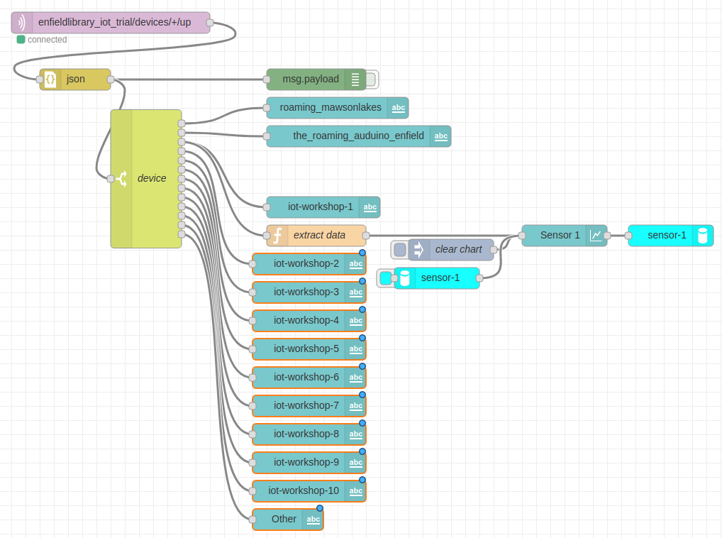
A Node-RED flow configured to process IoT data.
Data collected by The Things Network is pulled into Node-RED by using the MQTT node. This requires the name of The Things Network application and an application key/password.
Add an MQTT node and add a new mqtt-broker (server)
Name: Something memorable eg. Meshed
Connection
Server: thethings.meshed.com.au
Port: 1883
SSL/TLS: (Unchecked)
Use Legacy MQTT 3.1 support: (Checked)
Security
Username: enfieldlibrary_iot_trial
Password: (application-key copied from TTN website, starts with ‘ttn-account-v2’)
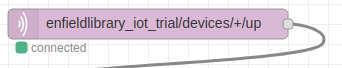
The topic is the MQTT channel to subscribe to where ‘+’ is a wildcard and will match any device name.
enfieldlibrary_iot_trial/devices/+/up
There are a range of channels defined in the The Things Network API[1] covering different types of messages. Eg. up, down.
Node Decription
MQTT client
This node connects to The Things Network and subscribes to the defined topic. Any data sent by our LoRaWAN devices will be sent out this node.
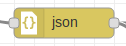
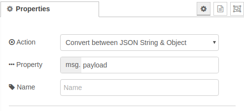
JSON
This node converts a text payload to JSON format. This is useful for allow later nodes to access individual parts of the payload.
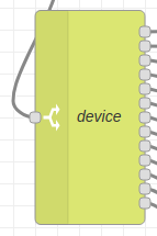
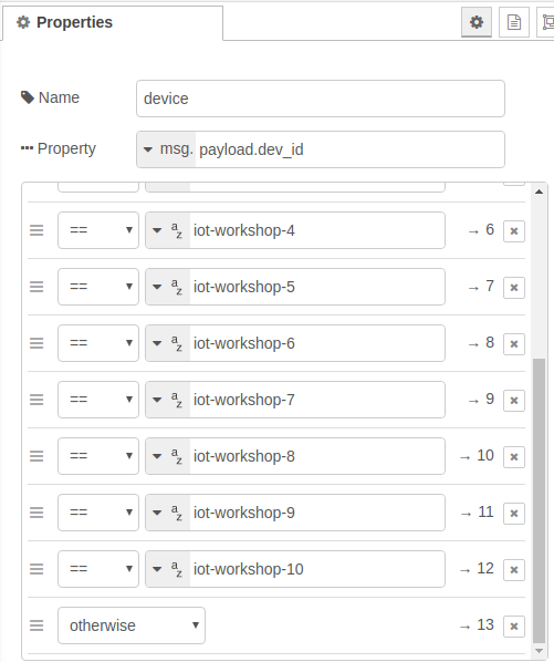
Switch
Diverts messages between different processing flows. In the above flow, it is being used to send device data to different dashboard labels. This allows us to display the latest data coming from each sensor.
Function
Code can be written in JavaScript to manipulate the messages passed to the node.
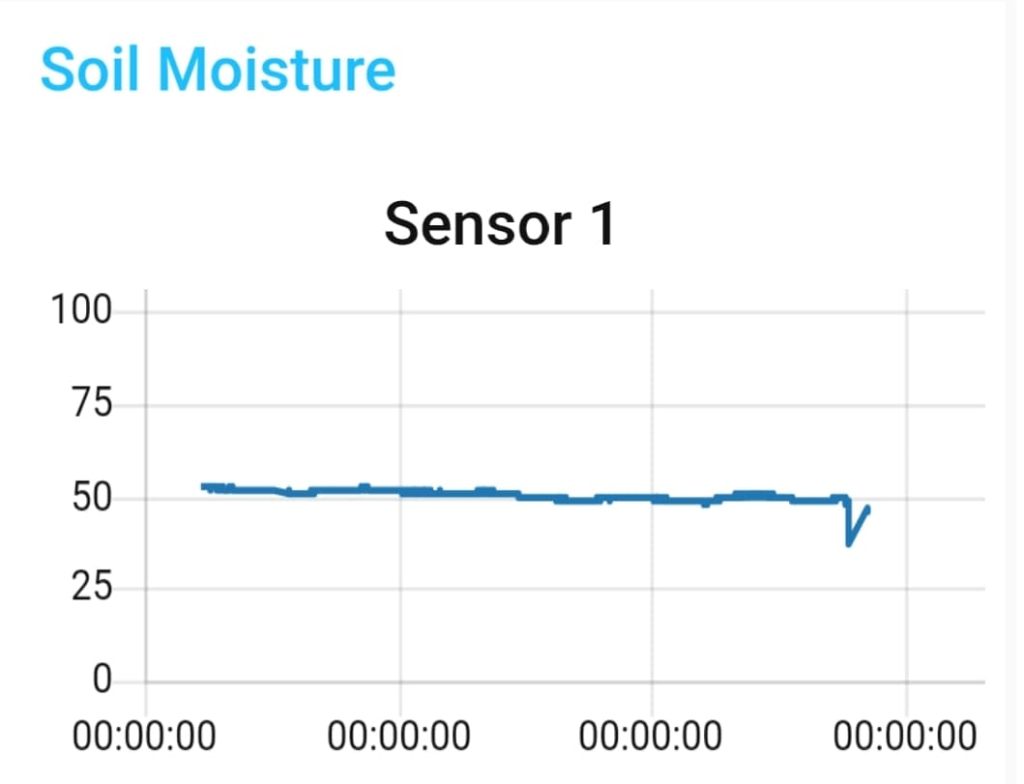
In our example we take the data transmitted by our device and received by The Things Network (eg. Sensor: 0x0267)[2], extract the data (substring) and convert to a meaningful number (moisture). This is passed directly to the next node in the payload of the message (the ‘msg’ variable).
var payload = msg.payload.payload_fields.receivedString
payload = payload.substring(10)
var integer = parseInt(payload,16)
var moisture = integer/1024.0 * 100.0
msg.payload = moisture

// To allow plotting of multiple series
msg.label = "sensor-1"

return msg;
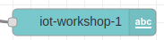
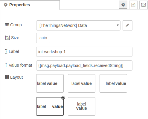
Dashboard Label
Creates label elements to display on the dashboard. These are updated by messages.
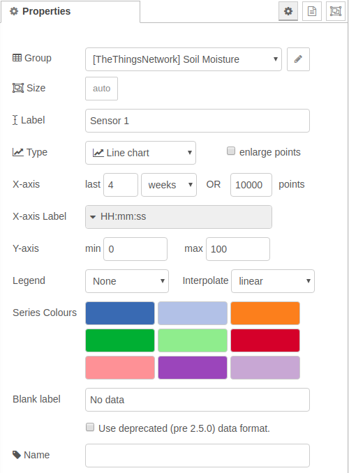
Dashboard Graph
Displays a graph from data. By default, the data is not permanantly stored and will not persist between flow deployments. The graph data can be stored persistantly by including save and restore nodes.
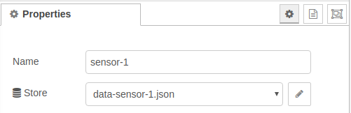
Persist (Save Data / Restore Data)
These nodes are used to ensure that the graphed data is persistent between reboots. Under particular conditions the date is written to a non-volatile location, and is read back into the system when starting up.
Multiple sets of data can be saved, but the save and restore nodes need to match.
The nodes above can be used in Node-RED to receive, display, graph and store data from LoRaWAN enabled sensors. It is a general purpose system and as such is missing some of the whistles and bells of some other systems.
Improvements can be made by hooking in some additional software packages. In particular, data can be stored in a database specifically designed to hold time series of sensor data (eg. InfluxDB[1]) and a more functional dashboard can be added for better graphing and analysis (eg. Grafana[2]).
In the previous post we discussed the LoRaWAN network and gave an overview of how it works end to end. This post looks in more detail and describes what’s necessary to get data into the network from individual sensors.
The LoRa Radio and LoRaWAN
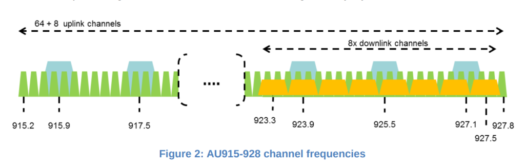
The LoRa radio module transmits in the Industrial , Scientific and Medical (ISM) unlicensed radio band[1]. In Australia (and New Zealand) LoRa transmits between 915-928 MHz[2]. For uploading data, the band is divided into 64 narrow bandwidth channels of 125 kHz, with an additional 8 overlapping broader channels of 500 kHz.
The data is encoded using a chirp signal. The rate that this frequency changes is defined by a ‘spreading factor’ (SF), and a doubling of the spreading factor approximately doubles the amount of time it take to transmit data[3].
LoRaWAN Channel Allocation for Australia and New Zealand
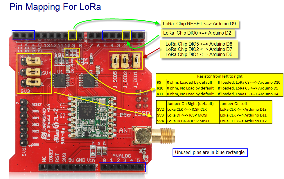
To use LoRa and LoRaWAN we are using the following LoRaWAN Arduino Shield available from the local suppliers. It is supplied to transmit and receive in the 915 MHz. As purchased the jumpers were not set, and needed to be installed as indicated in the picture below.
When developing hardware, it is only possible to use digital input/outputs 3,4 and 5 (3 lines). Digital IO 0 and 1 are used by serial IO and interfere with programmng. The digital lines D11-13 are used to control the LoRa radio.
The available Arduino pins for projects are
D3-5 (3 digital lines) – Can be sed for Digital IO
D0-1 (2 digital lines) – Can be used for Digital IO but interferes with in circuit programming. Needs to be disconnected first.
A0-5 – Canbe used for Analog Input or Digital IO
SCL,SDA – Can be used for Digital IO and Analog In on Arduni Uno.
AREF – Used as analog reference voltage
GND – Ground
Software
Arduino Library for LoRaWAN (LMIC)
The Arduino LMIC library that we are using is being maintained by Thomas Laurenson and can be found on Github[1]. The original LMIC Library was written by IBM and has been ported for use with the Arduino board.
Once downloaded and installed in the Ardiuino IDE library directory[2], the software needs to be configured to use the Australian frequency plan which is done by editing the file ‘project_config/lmic_project_config.h’. For some reason the Australian configuration is called CFG_au921.
Notes: [1] Github: https://github.com/thomaslaurenson/arduino-lmic [2] When unzipping the software, there may be duplicated recursive top level directory names (eg. arduino-lmic/arduino-lmic). Ensure that only one level is copied into Arduino library folder.
Example Arduino Sketch
An example Arduino sketch also available from the GitHub repository, which can be used to connect to the LoRaWAN network. See arduino-lmic/examples/ttn-otaa-dragino-lorashield-au915[1].
When connecting to the LoRaWAN network there are two authentication methods “Authtication by Personalisation” (ABP) and “Over the Air Authentication” (OTAA). While it is a little more complicated, OTAA is preferred as it allows the network more control over the authentication process, but requires two-way communication with the end-node. ABP does not require the end-node to receive data from the network but the network needs to know when the end-node is ever reset[2].
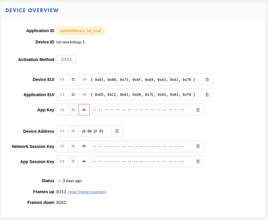
For OTAA, there are three pieces of data that need to be copied into the sketch, and are obtained from The Things Network console[3].
Device EUI (DEVEUI) – This is the unique identifier for this device on the network. This can be changed. This needs to be used in the sketch in Least Significant Byte (lsb) order.
Application EUI – This is the application identifier, and is unique across the LoRAWAN network. This needs to be used in the sketch in Least Significant Byte (lsb) order.
Application Key – This is an initial encryption key shared between the Node and Application. It can be changed. This needs to be used in sketch in Most Significant Byte (msb) order.
The webpage tries to make this as easy as possible by allowing you to adjust the formatting and the copy to clipboard button.
Device confiuration parameters in The Things Network
These details are copied into the Arduino sketch in the FILLMEIN locations as shown below.
// This EUI must be in little-endian format, so least-significant-byte
// first. When copying an EUI from ttnctl output, this means to reverse
// the bytes. For TTN issued EUIs the last bytes should be 0xD5, 0xB3,
// 0x70.
static const u1_t PROGMEM APPEUI[8]= { FILLMEIN };
void os_getArtEui (u1_t* buf) { memcpy_P(buf, APPEUI, 8);}

// This should also be in little endian format, see above.
static const u1_t PROGMEM DEVEUI[8]= { FILLMEIN };
void os_getDevEui (u1_t* buf) { memcpy_P(buf, DEVEUI, 8);

// This key should be in big endian format (or, since it is not really a
// number but a block of memory, endianness does not really apply). In
// practice, a key taken from the TTN console can be copied as-is.
static const u1_t PROGMEM APPKEY[16] = { FILLMEIN };
void os_getDevKey (u1_t* buf) {  memcpy_P(buf, APPKEY, 16);}
In the sketch, the following line can also be changed.
static uint8_t mydata[] = "OTAA"
This is the data that is going to transmitted over the network. This short string can be edited to something more meaningful. The sketch can then be compiled and installed, and if a LoRaWAN Gateway is within range, transmitted data will start to be collected by The Things Network Application.
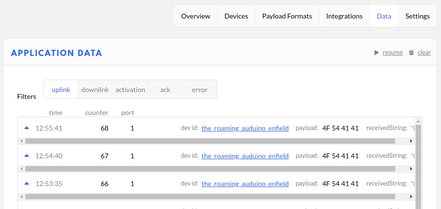
The transmitted packet data will appear under the Application Data on The Things Network.
Data packets being received from an IoT device via LoRaWAN
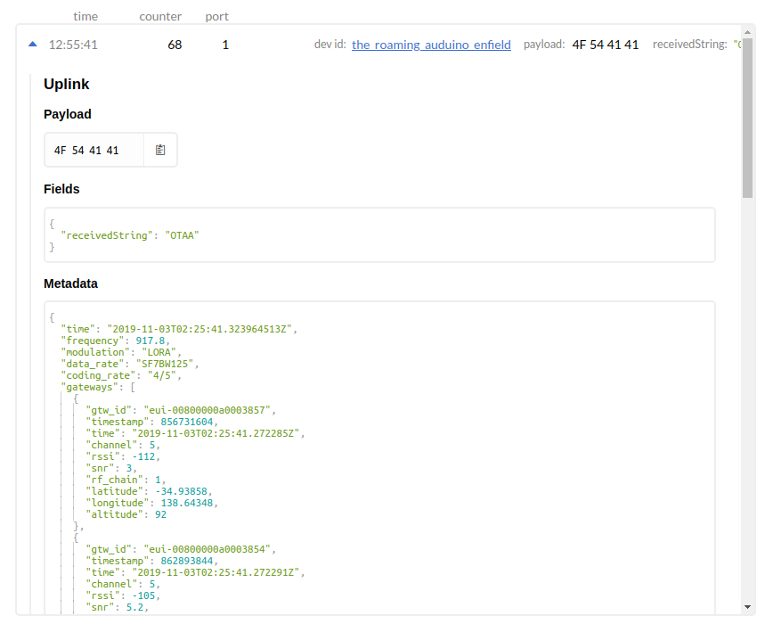
The information includes the data transmitted by the IoT device and metadata from the network about the transmission. Expanding the packet entry shows this detail.
In the case above, to assist with debugging a custom Payload Format decoder has been added which converts the bytes to a string with can be seen in the ‘receivedString’ field[1].
// Decode an uplink message from a buffer
// (array) of bytes to an object of fields.
function Decoder(bytes, port) {
   // var decoded = {};
   // if (port === 1) decoded.led = bytes[0];
   // return decoded;

   // Decode plain text; for testing only
   return {
       receivedString: String.fromCharCode.apply(null, bytes)
   };
 }
The raw transmitted data can be seen in the Payload.
The metadata fields show the frequency used (917.8 MHz), the datarate (SF7BW125 – Spreading Factor 7, Bandwidth 125 kHz) and the gateways which heard the transmission and their details.
The next step will be to look at how to make use of the collected data. NodeRed is a software package will be used to process and manipulate the data as it is received.
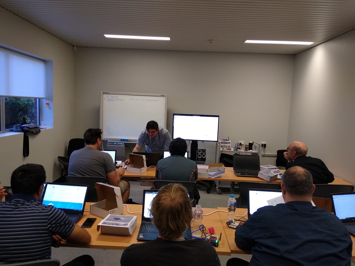
On Thursday (24 Oct 2019) we started running the first session of a new IoT workshop, being held at the local libray (Enfield Branch of the Port Adelaide Enfield Council). This workshop aims to be an introduction to creating sensors and nodes for the LoRaWAN IoT network, using The Things Network website.
This first sesssion (of four) was a whirlwind dump of details which we will unpack and work on through the remainder of the sessions, with hands on electroncs and programming.
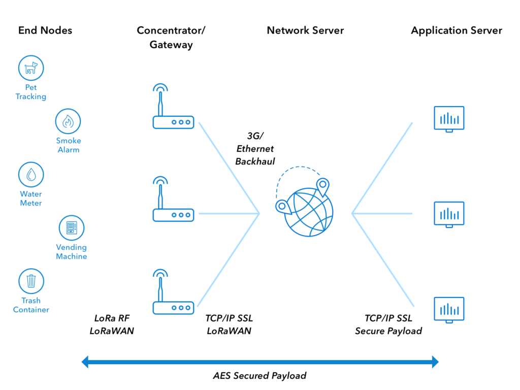
We went though the architecture of the system and got everyone to create an account on The Things Network, and set them up so that they could see the IoT data that was being transmitted over the network.
Architecture of LoRAWAN Network (from The Things Network)
Technolgy discussed..
A quick summary of the various bits-n-pieces that are being used follows.
LoRa
The radio technology that is used by sensors for ‘Long Range’, low bandwidth communication. These radios may be programmed to be used in either point-to-point or point-to-gateway (LoRaWAN) mode, configurable with software. They use the unlicensed ISM radio bands, 911MHz in Australia.
The radio network and infrastructure used to collect sensor data, via publically accessible gateways.
Arduino
A microprocessor board and programming tools, which use the Atmel (and other) microprocessor. The original aim was to create a programming system which was easy to use for hobbyists and members of the maker community. Arduino microprocessor boards can be used with a LoRa radio to create sensors which can transmit data via LoRAWAN and the internet to be collected and used by other applications. https://www.arduino.cc/
Arduino Shield
This is additional hardware that has been designed to plug directly into an Arduino board and allow it to be easy to use.
Arduino IDE
The Interactive Development Environment (IDE) used to program an Arduino microprocessor board. It is available as a downloadable Java program, and as a web based application. The software is available from the Arduino website.
Arduino Libraries
Additional software packages which can be installed to extend Arduino programs. For example, the LMIC library is used to allow our Arduino programs to use the LoRaWAN radio shield.
Libraries can be downloaded from within the Arduino IDE, or downloaded and installed manually.
LoRaWAN Sensor Node
A device which collects data and transmits to the LoRaWAN network. It uses a LoRa radio. They need to be registered and authenticated with the LoRaWAN network to transmit correctly.
LoRaWAN Gateway
A device which listens for LoRaWAN radio transmissions from nodes in its area and forwards them to the servers on the LoRaWAN network. They need to be connected to the internet and be registered to operate.
The Things Network
A free website (registration required) which allows access to data collected by LoRaWAN sensors. It is used to register LoRaWAN gateways on the network, and create LoRaWAN applications.
MQ Telemetry Transport. This is the communication software and protocol used to allow sensor data to be distributed and used once it has been collected by The Things Network.
NodeRed
A web server program, which can be installed on a home computer or server (or Raspberry Pi) which can collect and use sensor data collected. It uses MQTT to access sensor data.
NodeRed is an automation environment and is useful for a lot more than collecting and displaying our IoT data. See the website for more details.
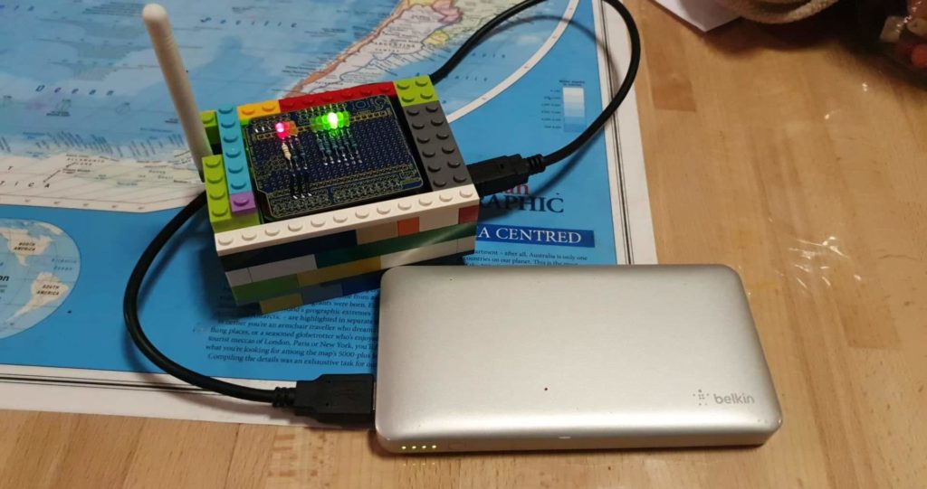
While the kids had the Lego out, I thought that I would pinch some pieces and build a case for my LoRaWAN node. Nothing fancy, random colours but enought to protect the boards from random knocks and bumps.
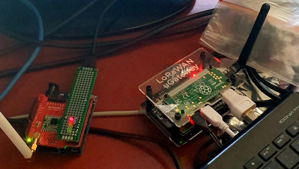
LoRa Node consisting of an Arduino Uno (bottom), Duinotech LoRa Radio shield (middle) and Freetronics prototyping board (top)
The following is a quick update on the construction of LoRaWAN node., which was perviously described here.
After the previous work and the messing around with the uneven Arduino pins, I ordered some Freetronics prototyping boards and continued with those.
With the first prototype, I had attached LEDs to the first two digital pins (D0,D1) which are also used by the USB Serial connection. These made them kind of useless for monitoring any status, but also interfeared with the Arduino sketch programming. Before a new program could be successfully loaded in this configuration, the board first needed to be removed. This got annoying very quickly, particularly when I enjoy having a fast development process.
In the next design I removed these LED’s and connected them up to the supposibly free and available digital pins (D11,D12 and D13). It appears as though the LoRa radio board also uses at least one of these pins out of the box, with configuration jumpers that use the others. If the configuration jumpers are changed, the software would also need to be changed. The board works as expected out of the box with the available Arduino libraries, so it would be a pity to mess this up. Also, the documentation on the boards jumpers, and their orientation isn’t the clearest, so it would be best just to leave this well alone.
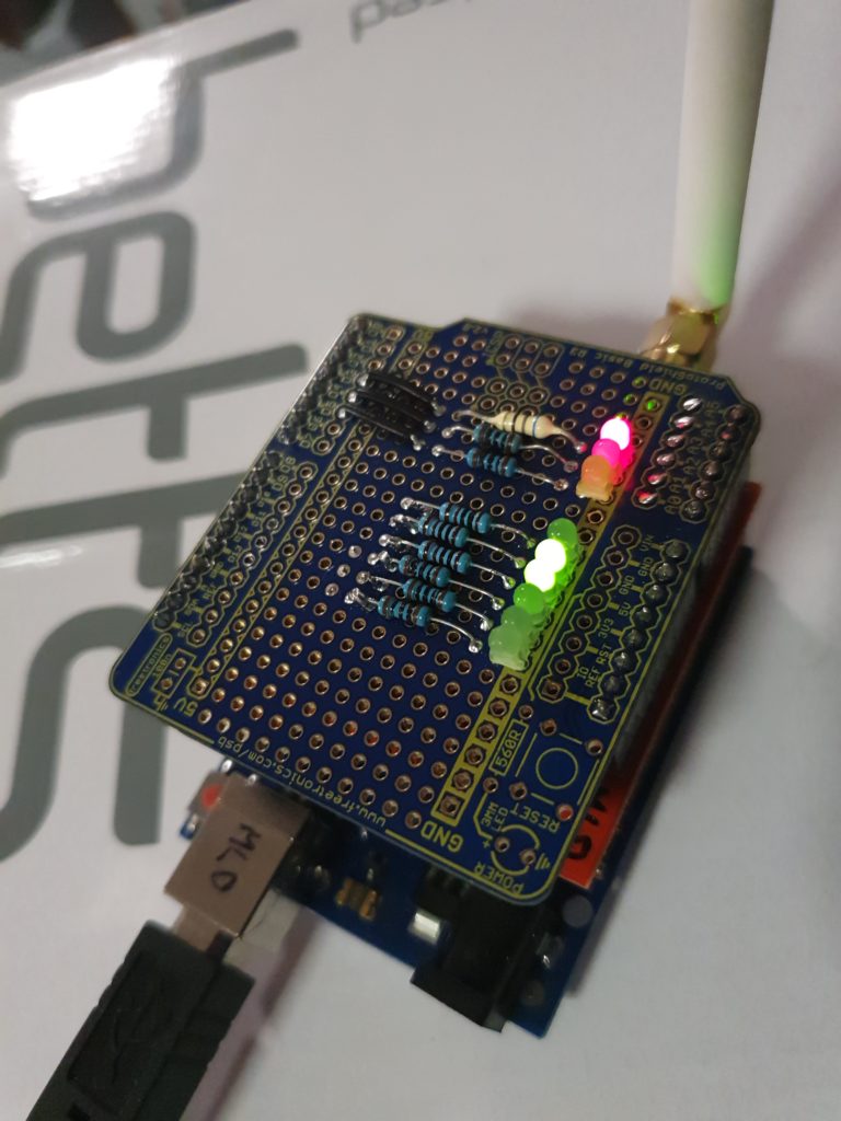
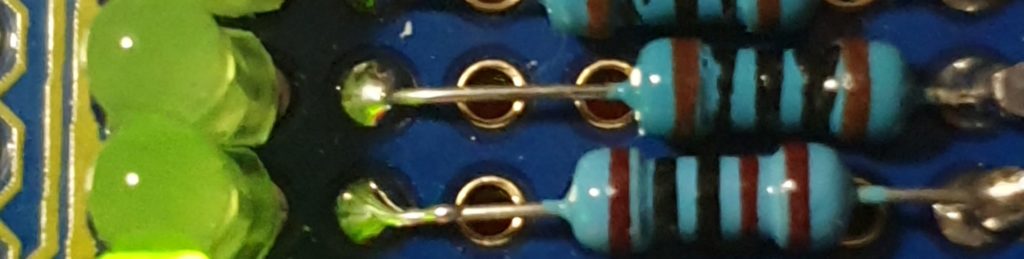
The remnants of this work can be seen on the bottom three resistors seen in the picture above. These resistors were connected with hookup wire underneath to pin D11, D12 and D13.
The Arduinio analog input pins, which were still unuised, can be switch to be used as digital outputs. The three LEDs that were connected earlier to the digital pins, were now connected to Analog pins A0, A1 and A2, with addional LEDs (with resistors, more about that sortly) to A3, A4, and A5. They are connected by more hookup wire underneath the prototype board.
Spot the difference.
A sketch was written to test the connected LED’s and was uploaded, without having to remove the prototype board first. This showed that everything was working as expected, except for one thing. The three new LEDs where significantly dimmer than the first ones.
The three new resistors I had grabbed quickly from my resistor box were 1K (Brown-Black-Black-Brown/Brown), rather than 100 Ohm (Brown-Black-Black-Black/Brown). This ment that the current through the LEDs was less, and hence their brightness was less as well. This has not been fixed in this prototype and probably wont be, although I could solder another suitably size resistor in parallel to the 1K ones to made the combined resistance close to the desired 100 Ohm amount.
The uploaded sketch was still contained the ability to set a couple of LEDs based on a byte of data received from the LoRaWAN radio. This was shown to work from The Things Network web, with the next step being able to drive this from custom software. Data from the LoRaWAN node is accesses via the MQTT protocol, and data can be uplinked to the node using the same method.
With assistance of the STEM Education resources from the Port Adelaide Enfield Libraries, I have been investigating LoRaWAN devices, how to build them and how they can be used.
There is more investigation to be done, but the node shown in the picture above is able to do the following:
Connect and Authenticate to a LoRaWAN network (The Things Network) via Over The Air Authentication (OTAA); and
Send data (Uplink) and Receive data (Downlink) via the LoRaWAN Gateway(s). (Downlink data is queued, and is received in a window after Uplink data has been received by the network. This reduces power usage in the node.)
The Node used was the Gragino Arduino Shield (or clone from duinotech)
The Gateway is the uGateway LoRaWAN from Core Electronics. Having a local gateway is not necessary if there is another one in the neighbourhood, within range of your node. There are currently no nodes in my area so an internal gateway was required for development and testing. The other option was to take the Node for a drive in the car after a development session, but this made debugging very tiresom, very quickly.
There are a couple of other useful tools worth mentioning.
TTN Mapper is an Android application that will monitor your device on your smart phone, via The Things Network. It then used your phones GPS to log the position of your device. The result is that you can map the coverage of nearby gateways by using your LoRaWAN node and phone in a similar way to how Wireless Access points used to be mapped (WarDriving). This is useful for knowing where your nodes have TTN access, and where additional gateways might be required.