The following is a quick update on the construction of LoRaWAN node., which was perviously described here.
After the previous work and the messing around with the uneven Arduino pins, I ordered some Freetronics prototyping boards and continued with those.
With the first prototype, I had attached LEDs to the first two digital pins (D0,D1) which are also used by the USB Serial connection. These made them kind of useless for monitoring any status, but also interfeared with the Arduino sketch programming. Before a new program could be successfully loaded in this configuration, the board first needed to be removed. This got annoying very quickly, particularly when I enjoy having a fast development process.
In the next design I removed these LED’s and connected them up to the supposibly free and available digital pins (D11,D12 and D13). It appears as though the LoRa radio board also uses at least one of these pins out of the box, with configuration jumpers that use the others. If the configuration jumpers are changed, the software would also need to be changed. The board works as expected out of the box with the available Arduino libraries, so it would be a pity to mess this up. Also, the documentation on the boards jumpers, and their orientation isn’t the clearest, so it would be best just to leave this well alone.
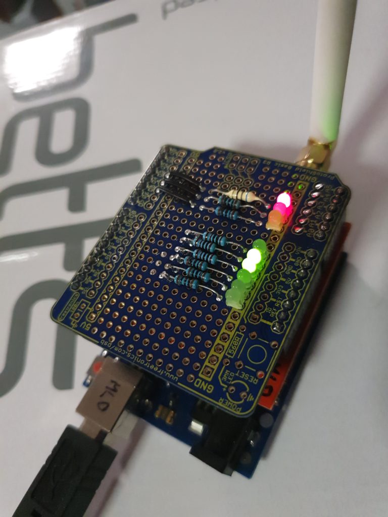
The remnants of this work can be seen on the bottom three resistors seen in the picture above. These resistors were connected with hookup wire underneath to pin D11, D12 and D13.
The Arduinio analog input pins, which were still unuised, can be switch to be used as digital outputs. The three LEDs that were connected earlier to the digital pins, were now connected to Analog pins A0, A1 and A2, with addional LEDs (with resistors, more about that sortly) to A3, A4, and A5. They are connected by more hookup wire underneath the prototype board.
A sketch was written to test the connected LED’s and was uploaded, without having to remove the prototype board first. This showed that everything was working as expected, except for one thing. The three new LEDs where significantly dimmer than the first ones.
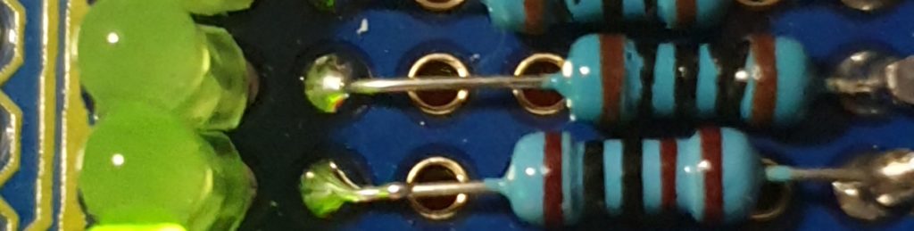
The three new resistors I had grabbed quickly from my resistor box were 1K (Brown-Black-Black-Brown/Brown), rather than 100 Ohm (Brown-Black-Black-Black/Brown). This ment that the current through the LEDs was less, and hence their brightness was less as well. This has not been fixed in this prototype and probably wont be, although I could solder another suitably size resistor in parallel to the 1K ones to made the combined resistance close to the desired 100 Ohm amount.
The uploaded sketch was still contained the ability to set a couple of LEDs based on a byte of data received from the LoRaWAN radio. This was shown to work from The Things Network web, with the next step being able to drive this from custom software. Data from the LoRaWAN node is accesses via the MQTT protocol, and data can be uplinked to the node using the same method.
I have created several utility scripts to test all of this, which can be found on GitHub at: https://github.com/PaulSchulz/ttn-utils