In the previous post we discussed the LoRaWAN network and gave an overview of how it works end to end. This post looks in more detail and describes what’s necessary to get data into the network from individual sensors.
The LoRa Radio and LoRaWAN
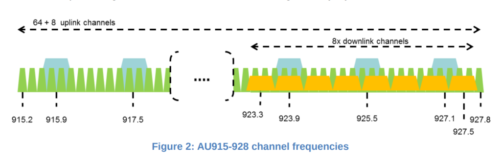
The LoRa radio module transmits in the Industrial , Scientific and Medical (ISM) unlicensed radio band[1]. In Australia (and New Zealand) LoRa transmits between 915-928 MHz[2]. For uploading data, the band is divided into 64 narrow bandwidth channels of 125 kHz, with an additional 8 overlapping broader channels of 500 kHz.
The data is encoded using a chirp signal. The rate that this frequency changes is defined by a ‘spreading factor’ (SF), and a doubling of the spreading factor approximately doubles the amount of time it take to transmit data[3].
Notes:
[1] ISM Band – https://en.wikipedia.org/wiki/ISM_band
[2] https://lora-alliance.org/sites/default/files/2018-05/lorawan_regional_parameters_v1.0.2_final_1944_1.pdf
[3] https://medium.com/home-wireless/testing-lora-radios-with-the-limesdr-mini-part-2-37fa481217ff
Hardware
Dragino Arduino Shield
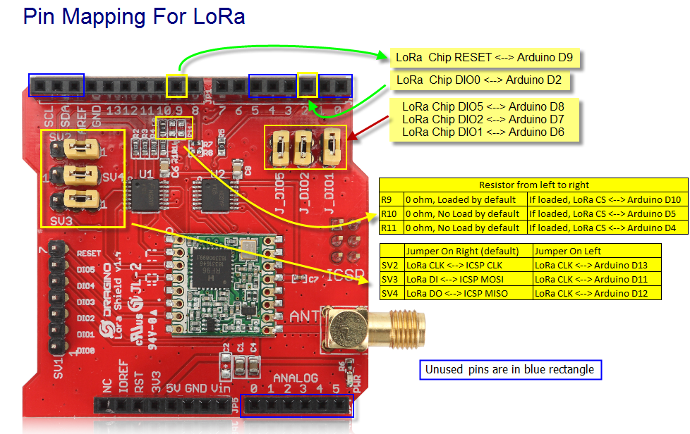
To use LoRa and LoRaWAN we are using the following LoRaWAN Arduino Shield available from the local suppliers. It is supplied to transmit and receive in the 915 MHz. As purchased the jumpers were not set, and needed to be installed as indicated in the picture below.

When developing hardware, it is only possible to use digital input/outputs 3,4 and 5 (3 lines). Digital IO 0 and 1 are used by serial IO and interfere with programmng. The digital lines D11-13 are used to control the LoRa radio.
The available Arduino pins for projects are
- D3-5 (3 digital lines) – Can be sed for Digital IO
- D0-1 (2 digital lines) – Can be used for Digital IO but interferes with in circuit programming. Needs to be disconnected first.
- A0-5 – Canbe used for Analog Input or Digital IO
- SCL,SDA – Can be used for Digital IO and Analog In on Arduni Uno.
- AREF – Used as analog reference voltage
- GND – Ground
Software
Arduino Library for LoRaWAN (LMIC)
The Arduino LMIC library that we are using is being maintained by Thomas Laurenson and can be found on Github[1]. The original LMIC Library was written by IBM and has been ported for use with the Arduino board.
Once downloaded and installed in the Ardiuino IDE library directory[2], the software needs to be configured to use the Australian frequency plan which is done by editing the file ‘project_config/lmic_project_config.h’. For some reason the Australian configuration is called CFG_au921.
// project-specific definitions
//#define CFG_eu868 1
//#define CFG_us915 1
define CFG_au921 1
//#define CFG_as923 1
// #define LMIC_COUNTRY_CODE LMIC_COUNTRY_CODE_JP       /* for s923-JP */
//#define CFG_in866 1
define CFG_sx1276_radio 1
//#define LMIC_USE_INTERRUPTS
Notes:
[1] Github: https://github.com/thomaslaurenson/arduino-lmic
[2] When unzipping the software, there may be duplicated recursive top level directory names (eg. arduino-lmic/arduino-lmic). Ensure that only one level is copied into Arduino library folder.
Example Arduino Sketch
An example Arduino sketch also available from the GitHub repository, which can be used to connect to the LoRaWAN network. See arduino-lmic/examples/ttn-otaa-dragino-lorashield-au915[1].
When connecting to the LoRaWAN network there are two authentication methods “Authtication by Personalisation” (ABP) and “Over the Air Authentication” (OTAA). While it is a little more complicated, OTAA is preferred as it allows the network more control over the authentication process, but requires two-way communication with the end-node. ABP does not require the end-node to receive data from the network but the network needs to know when the end-node is ever reset[2].
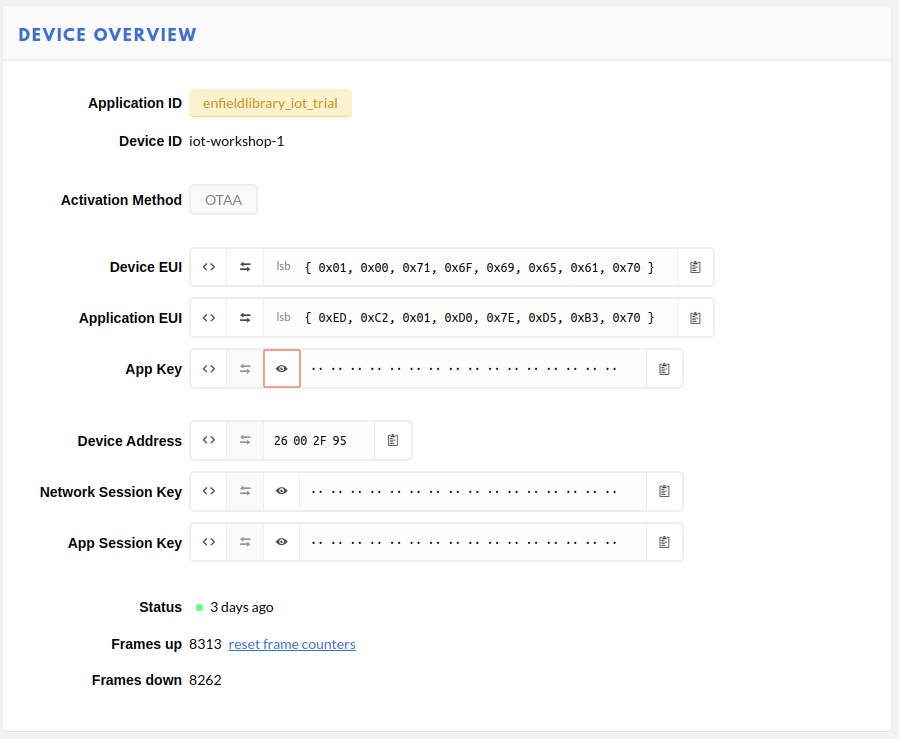
For OTAA, there are three pieces of data that need to be copied into the sketch, and are obtained from The Things Network console[3].
- Device EUI (DEVEUI) – This is the unique identifier for this device on the network. This can be changed. This needs to be used in the sketch in Least Significant Byte (lsb) order.
- Application EUI – This is the application identifier, and is unique across the LoRAWAN network. This needs to be used in the sketch in Least Significant Byte (lsb) order.
- Application Key – This is an initial encryption key shared between the Node and Application. It can be changed. This needs to be used in sketch in Most Significant Byte (msb) order.
The webpage tries to make this as easy as possible by allowing you to adjust the formatting and the copy to clipboard button.
These details are copied into the Arduino sketch in the FILLMEIN locations as shown below.
// This EUI must be in little-endian format, so least-significant-byte
// first. When copying an EUI from ttnctl output, this means to reverse
// the bytes. For TTN issued EUIs the last bytes should be 0xD5, 0xB3,
// 0x70.
static const u1_t PROGMEM APPEUI[8]= { FILLMEIN };
void os_getArtEui (u1_t* buf) { memcpy_P(buf, APPEUI, 8);}

// This should also be in little endian format, see above.
static const u1_t PROGMEM DEVEUI[8]= { FILLMEIN };
void os_getDevEui (u1_t* buf) { memcpy_P(buf, DEVEUI, 8);

// This key should be in big endian format (or, since it is not really a
// number but a block of memory, endianness does not really apply). In
// practice, a key taken from the TTN console can be copied as-is.
static const u1_t PROGMEM APPKEY[16] = { FILLMEIN };
void os_getDevKey (u1_t* buf) {  memcpy_P(buf, APPKEY, 16);}
In the sketch, the following line can also be changed.
static uint8_t mydata[] = "OTAA"
This is the data that is going to transmitted over the network. This short string can be edited to something more meaningful. The sketch can then be compiled and installed, and if a LoRaWAN Gateway is within range, transmitted data will start to be collected by The Things Network Application.
Notes:
[1] Github: https://github.com/thomaslaurenson/arduino-lmic/tree/master/examples
[2] The packet counters need to be reset. This is used to stop data ‘replay’ attacks.
[3] Console->Applicaion->Devices
LoRaWAN Data
The transmitted packet data will appear under the Application Data on The Things Network.
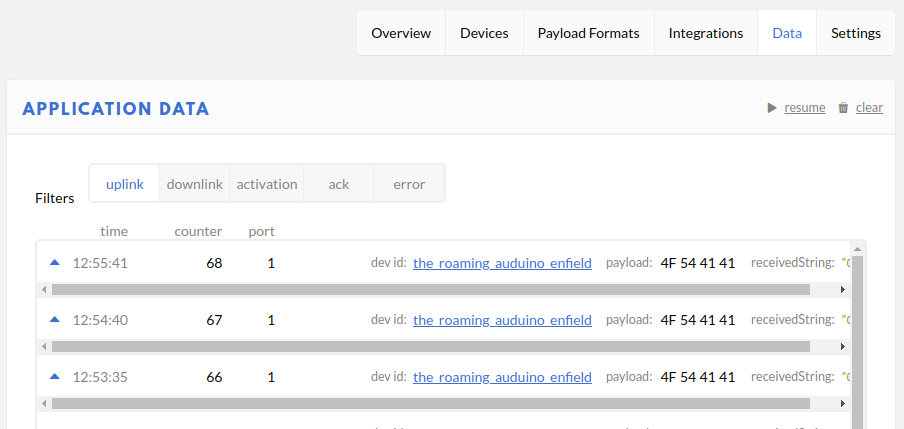
The information includes the data transmitted by the IoT device and metadata from the network about the transmission. Expanding the packet entry shows this detail.
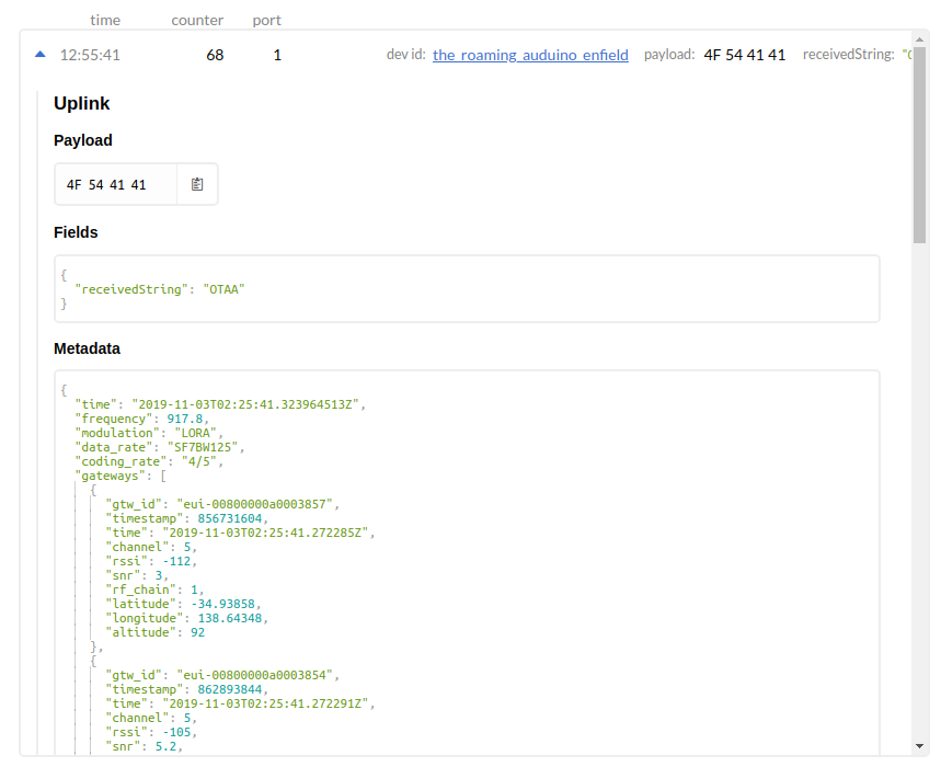
In the case above, to assist with debugging a custom Payload Format decoder has been added which converts the bytes to a string with can be seen in the ‘receivedString’ field[1].
// Decode an uplink message from a buffer
// (array) of bytes to an object of fields.
function Decoder(bytes, port) {
   // var decoded = {};
   // if (port === 1) decoded.led = bytes[0];
   // return decoded;

   // Decode plain text; for testing only
   return {
       receivedString: String.fromCharCode.apply(null, bytes)
   };
 }
The raw transmitted data can be seen in the Payload.
The metadata fields show the frequency used (917.8 MHz), the datarate (SF7BW125 – Spreading Factor 7, Bandwidth 125 kHz) and the gateways which heard the transmission and their details.
Notes:
[1] https://core-electronics.com.au/tutorials/encoding-and-decoding-payloads-on-the-things-network.html
Next Time (Part 3)
The next step will be to look at how to make use of the collected data. NodeRed is a software package will be used to process and manipulate the data as it is received.