At the recent Everything Open Conference, I attended a taik by Vic OIiver on the one handed keyboard called the Quirkey.
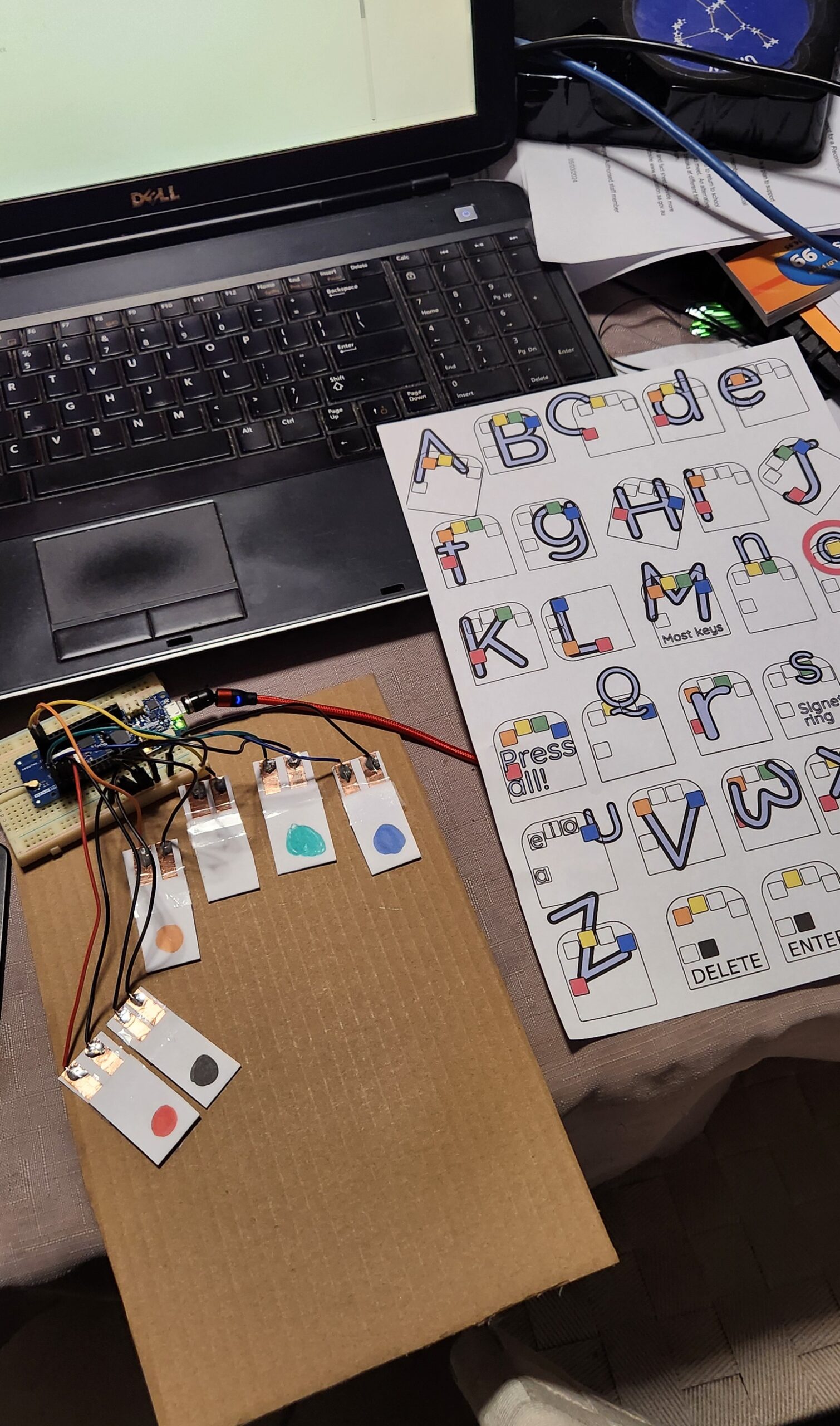
I am attempting to write this blog post using a version of this keyboard I have made out of cardboard, a Arduino MKR 1310 board and some other bits and pieces of stuff that I found lying around the house. (I am going to have to stop here and go back to my regular QWERTY keyboard. I will have another practice later, but at the moment I am finding that I am using the ‘backspace’ more than I would like to.)
While looking into the Arduino code, it occured to me that I had a dev board that would actually work with this code (the Arduino MKR 1310 which had been used in a previous project). In particular, this board supported the HID, and Keyboard and Mouse libraries, which is what allowed this board to appear as (surprise, surprise) a keyboard and mouse device when plugged into a USB port. There ae many naferious project ideas for this sort of technology, but I don’t think that the usefulness has been explored enough.
The Design
This project code takes the corded (multiple symaltanious keypress) inputs, of six buttons, and converts it into regular keyboard input. Vik’s presentation gives more of the backgound, and reasons why knowing how to use one handed keyboard is a good skill to have. In addition, the documentation includes helpful tools to assist in learning this skill, as will as a typing tutor.
So… I have an Arduno board that will do the job (there is a good list of supported boards on the HID Library page), I just need to get some switches.
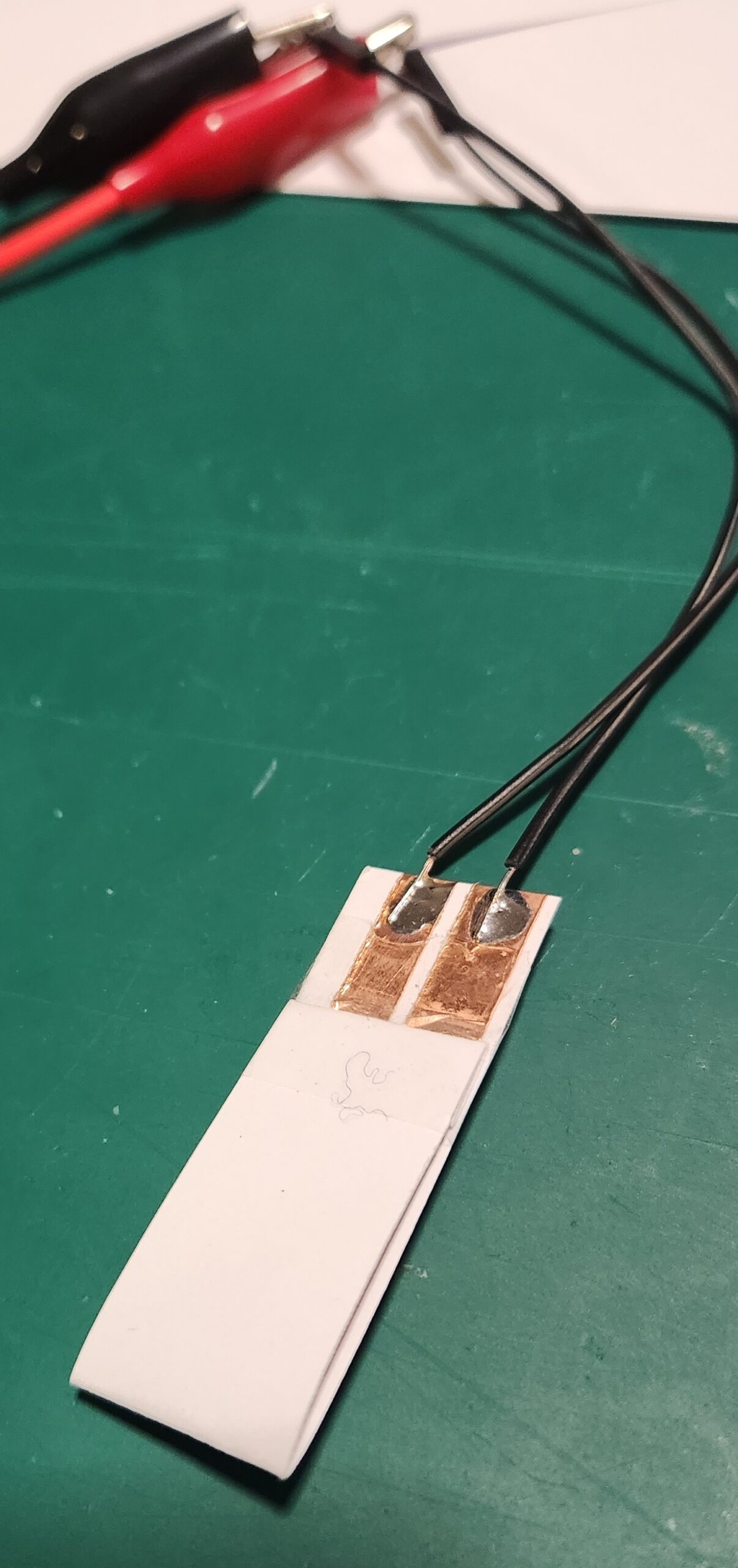
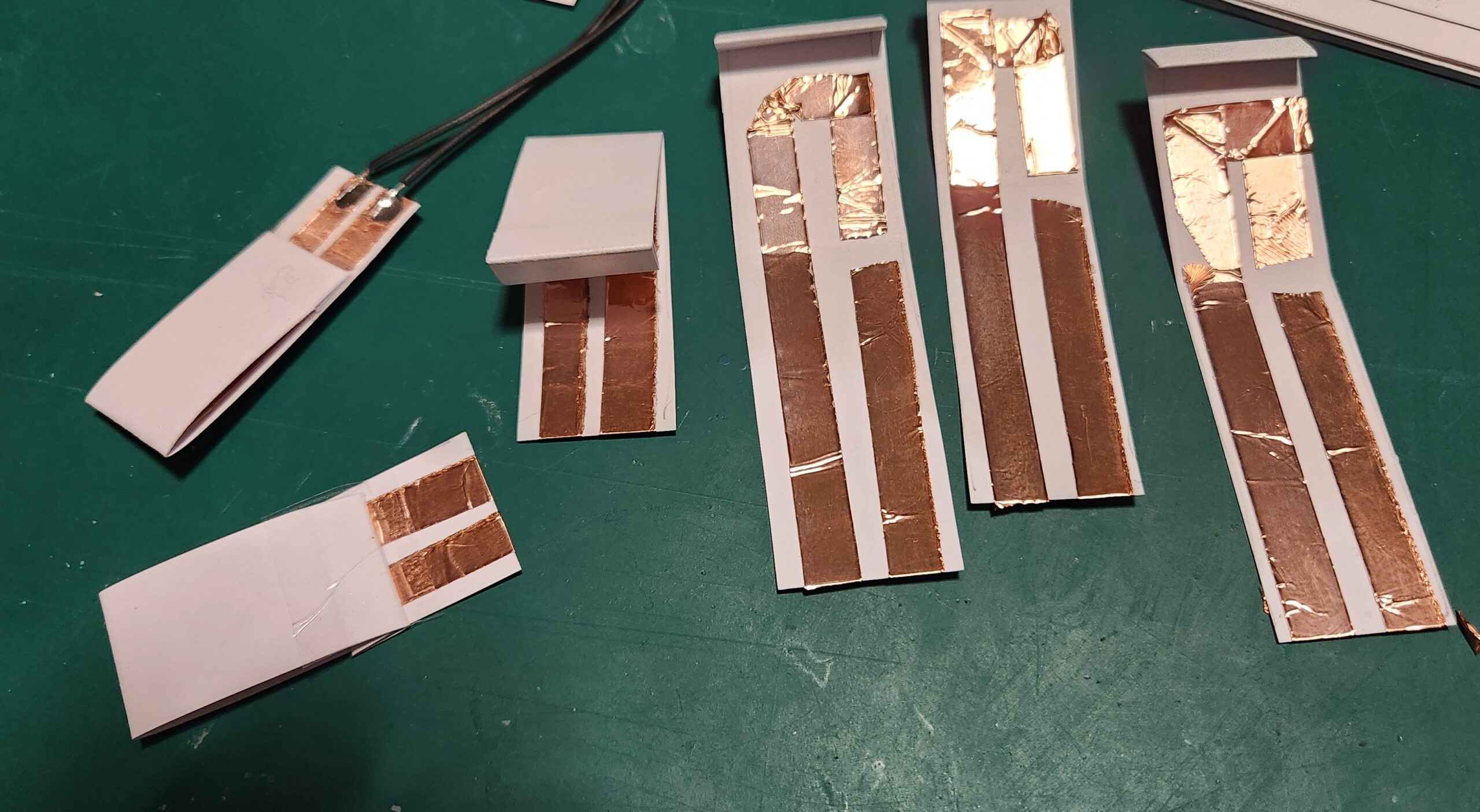
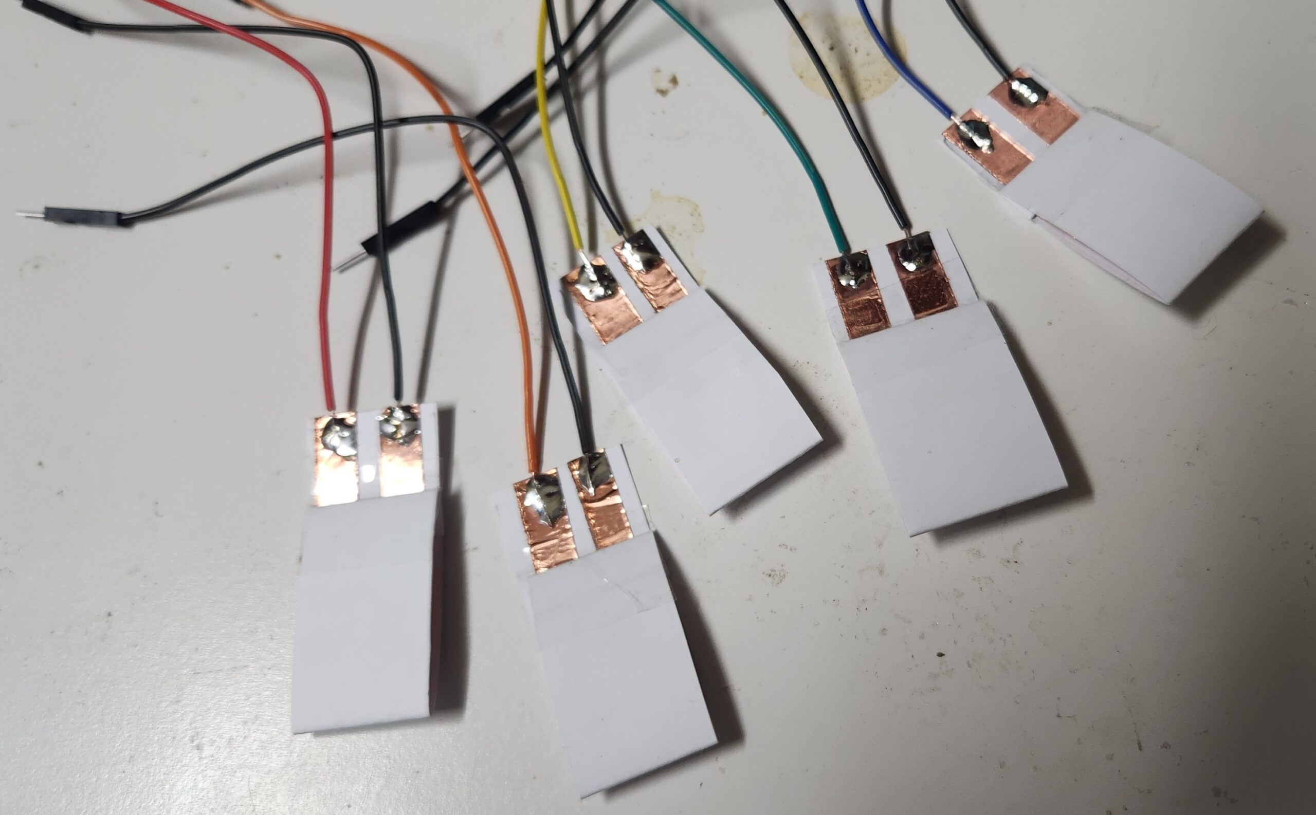
The latest version of the Quirkey keyboards were the result of lots of trial and erro experimentation, and consited of a 3D printed shell with six mechancal switches. My Prusa printer is currently broken and I didn’t have any unused mechanical switches within reach, but I did have some cardboard, copper tape and my trusty soldering iron. So, after some of my own experimentation, we get the following design…
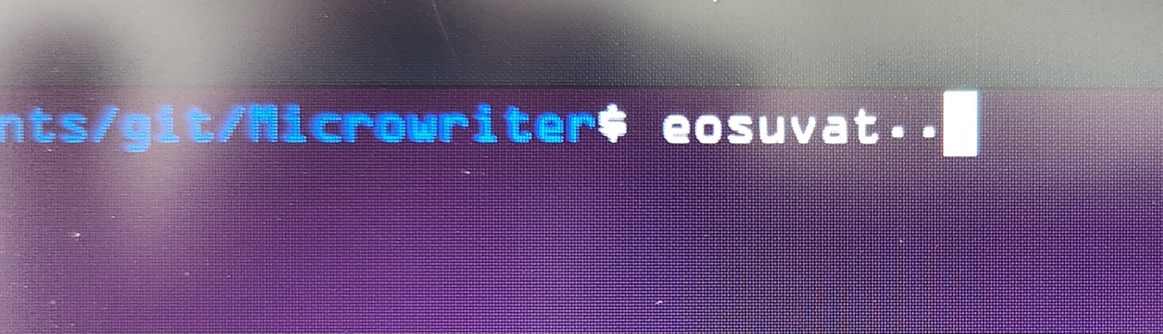
The cardboard switches are stuck down onto a piece of cardboard, wired up to the Arduino MKR 1310 board (any MKR 1000 series boar will work), and programmed with the MicroWriter Ardunio sketch. (Comments in the sketch indicate which pins connect to which switch.)
There is a 5 second delay on startup, but the board is now detected as an “Arduino LLC Arduino MKR WAN 1310 Keyboard” and “Arduino LLC Arduino MKR WAN 1310 Mouse”, and works as advertsed.
Conclusion
This is a great cheap-n-cheerful project incorporating a bunch of useful ‘maker’ techniques (soldering, wiring and Ardunio programming) which can be completed resonably quckly.. and at the end you get something useful to play with.
The switches aren’t perfect, but it’s great to have something to use to learn the one handed keyboard technique.
After practicing for a while, for not much more, the paper and copper switches and cardboard can be replaced with something a little more permanent. (A project for the future.)
It was a most enjoyable time exploring topics covering Free and Open Source Software (FOSS) topics, including some of the social and inclusivity issues.
The videos of the conference will be made available at some stage.
The Everything Open 2025 Conference will be held in Adelaide, so watch out for the announcements (and subscribe to the Linux Australia mailing list).
This article is part 1.5 of the series – Developing a component for ESPHome, for the SX1262 LoRa Radio Chip. The process getting the LoRaWAN functionality of this development board to work with The Things Network proved to be an excercise infrustration management, so the following is a write up of what was required to get it to work. The following is my account of setting up the Heltec Wireless Lite V3 for connecting to the LoRaWAN network. There were several false starts, but in the end it was possible to send data and decode it correctly.
Development Environment
ArduinoIDE and the Heltec Board Manager extention
The Heltec boards are defined by the following file (link) which is added through the menu in Preferences…->Additional boards manager URLs
This file specifies that esptool 3.3.0 is used for writing the firmware to the Heltec board. There is as issue with usung this version for the Heltec V3 boards, in that the firmware compiles and installs, but puts the ESP32-S3 processor into a boot loop.
Install the ‘SX126X-Arduino’ library with the library manager (currently version 2.4.0).
A small fix is required. Edit the ‘src/mac/Commissioning.h’ file and comment out the check for whether the LoRaWAN Region has already being set (Line 40).
Example Code – LoRaWAN.ino
From the LoRaWAN library, the LoRaWAN example was copied and modified to get the system to work.
Modifications:
Copy the LoRaWAN.ino file, and remove other unnecessary files. Fix the source to remove the dependancies.
Simplify the code. eg. Remove the code sections used for other processors.
Set the authentication mode to OTAA, the device type and the Frequency bandplan region to AU915 by adding the optional parameters to ‘lmh_init() – true, CLASS_A and LORAMAC_REGION_AU915.
Ensure that the correct LoRaWAN sub-band is being used for AU915 by calling ‘lmh_setSubBandChannels(2)’.
Additional Serial.println() output added to trace the execution of the firmware, including the output of the LoRaWAN parameters.
The LoRaWAN parameters (AppEUI, DevEUI and AppKey) are set in the following section.
The Things Network
The Heltec V3 Devices have not been configured as known devices in The Things Network, and need to be specifically setup.
Select “Enter end device specifics manually”.
Add a new device and set the following Device Parameters
Frequency Plan: Australia 915-928 MHz, FSB 2 (used by TTN)
LoRaWAN Version: LoRaWAN Specification 1.0.2
Regional Parameters version: RP001 Regional Parameters 1.0.2 revision B
Create a JoinEUI (previously known as the AppEUI). This can be freely set any 8-byte value, but cannot be changed once set.
The other parameters that need to be set are:
DevEUI
AppKey
The easiest way to to get these values is to allow them to be automatically generated by The Things Network interface. They can be specifically set if the manufacturer of a device has preprogrammed a device with a LoRaWAN configuration.
Build and Install Firmware on Device
Update the definitions of the LoRaWAN parameters in the code to reflect the values just generated. It is possible to directly produce the desired strings (in ‘msb’ format) from The Things Network device interface.
It is also helpful to also have these values displayed when the board os booted.
The firmware compiles and can be installed onto the Heltec board. On boot, it should connect to the LoRaWAN network and start transmitting packets of data.
Uplink Payload Formatter
On The Things Network, to check that the uploaded data is correct, the following JavaScript payload filter can be installed for the device, which will decode the data and (hopefully) display the correct string.
function decodeUplink(input) {
var result;
result = String.fromCharCode.apply(null, input.bytes);
return {
  data: {
    bytes: input.bytes,
    result: result
  },
  warnings: [],
  errors: []
};
}
Notes, Issues and Errors
When selecting and playing around with different LoRaWAN Versions and Regonal Parameters, it appears as though The Things Network does not reset LoRaWAN values properly. Changing the LoRaWAN version to 1.1.0 required the additional parameter ‘NwsKey’. If the LoRaWAN version is then set back to 1.0.2, this value becomes the one that is used for the AppKey. There is a note about this in The Things Network interface, but it is not obvious what is required.
Care needs to be taken when setting the nodeDevEUI and nodeAppEUI not to set them the wrong way around. If connection packets are being received from the device, but it isn’t able to authenticate, then the nodeDevEUI will be correct, but the other parameters (including LoRaWAN Version) may be wrong.
If only intermittent transmitted packets are seen in The Things Network, and the device is not able to authenticate, check that the firmware has selected and is using the correct LoRaWAN sub-band.
Selecting other LoRaWAN versions eg. 1.1.0 will require additional parameters to be set., namely NwsKey. This setting is not removed if the LoRaWAN version is set back to 1.0.2, and this value is then used instead of the nodeAppKey. This is a trap. The only way to fix this is to delete the device definition in The Things Network and start over.
Next Steps
Convert the Arduino LoRaWAN firmware to ESPHome. This will allow LoRaWAN to be able to be used with the other ESPHome functions, including support for all of the existing supported sensors and outputs, and also operate with Home Assistant. (This will be Part 2 of the “Developing a component for ESPHome, for the SX1262 LoRa Radio Chip” series.)
Test with the Helium network. Register the device on the Helium network and check that data is routed correctly.
Implement as Class B and Class C LoRaWAN device. The example code currently only uploads data. Class B and Class C deviced allow data to be downloaded as well, for device control.
Ensure that option “Add Python to PATH” is selected before installing the package.
Check that Python is installed
In a Windows ‘cmd’ window (command prompt).
python --version
=> Should return something like: Python 3.10.1
Install dependencies
pip3 install wheel
Install ESPHome
pip install esphome
Check installation
esphome version
=> Should return something like: Version: 2023.12.0
ESPHome is now installed, and can be run from the Windows CMD
Using ESPHome
Create/Edit YAML files
ESPHome is driven via YAML configuration files in the working directory. YAML (Yet Another Markup Language) files are text files which are formatted in a specific way. They can be edited with any tool which can edit text files. (MS Notepad is good, MS Word may cause problems. MS Visual Studio (Code) is a good place to start.)
Once installed, view available ESPhome options
esphome -h
A simple YAML file that works with the Heltec Wifi LoRa 32 V3, which can be extended, looks like the following. (Copy and save this file as ‘esphome-device.yaml’) To understand the parts of this fle and the YAML configuration options, see: https://esphome.io/
When the program is running, it can be interupted by pressing the key combination: Ctrl-C
Over the Air (OTA) Updates
If enabled in the YAML file, ESPHome also supports “Over the Air” updates. This means that if the ESP board is currently connected to a Wifi network then using this connection, it can be directly upgraded with new firmware.
This option can be selected during the ‘upload’ step. If the board is not connected with USB and only connected to Wifi, this will happen automatically.
Additional notes – For Linux Users
Using a Virtual Environment – venv
The above process is very similar when installing on Linux or MacOS. On Linux, it is possible to setup a ‘virtual environment’ (venv) for development by installing and using the ‘venv’ command. This will allow the local Python libraries to be installed and run separately to the system libraries. This is useful to allow the development environment to use more recent library versions and/or allow the development environment to use more stable version. This helps when debugging and tracking down issues that may be caused by libraries.
Ensire that you are working in the required local project directory (eg. with the ‘cd’ command)
With Python and Pip installed as installed, create the venv development environment in the current working directory.
To restart editing session in an existing venv enabled directory
Setup the venv environment again by using:
. venv/bin/activate
At this stage, it is also possible to install ESPHome directly from the GitHub development repository. This is useful for debugging, bug fixing and testing.
Install development version from the Github ESPHome repository
This requires that the ‘git’ lool has been installed. (Use ‘apt git install’ on Ubuntu.)
This post describes “Work in Progress”. I have deliberately decided to put these details together now as it has been possible to build something that ‘sort of’ works, in that all the pieces are there, ot nearly there. The end is in sight, albeit a reasonably long way away in time and effort.
The original aim was to make the SX1282 LoRa radio chip available, for both LoRa and LoRaWAN modes, directly in ESPHome. It is hoped that the use of the SX126X series of radio chips can be as easy as possible to use and in most cases wholly driven from the ESPHome YAML files. When creating an IoT device with a new dev board, this has been one of the frustrating pieces of the excercise, particularly when using the Arduino IDE and programmer.
At the present time, these boards are not available for selecting directly in the ESPHome YAML file (when using the Arduino framework). In order to make these boards work with the available version of ESPHome, the following YAML is required:
These board definitions are imported from the platform-espessif32 project here.
The LoRa Arduino Library
The Arduino library being used is beegee-tokyo/SX126X-Arduino, which itself is based on several other libraries. It appear to currently be the best and most maintained LoRa library available for these radio chips.
The files lora-sx126x.yaml and secret.yaml provide an example of how to use the component. To use with a working version of ESPHome, edit secret.yaml to add your local Wifi details, then run:
esphome run lora-sx126x.yaml
Development Comments
To get the component into a working state, this ESPHome component currently does some things which are not encouraged by the ESPHome Core and Component developers (see below).
It is always hoped that this component will become compliant enough to be included in ESPHome, but in the meantime, it can be included in your ESPHome build by either cloning this repository locally and adding an external_component with a local source; or by including the github repository directly as an external_component. See the External Components documentation for more details
If downloading and using as a local source for external component:
external_components:
- source:
    type: local
    path: esphome/components
  components: ["lora_sx126x"]
and, using directly from the Github source for an external component
If possible, the SX126x-Arduino library needs to be implemented natively in ESPHome, to make use of the native ESPHome SPI code.
By using the Library directly, it is uncertain at the moment whether this component can be used generally with other devices that use the same SPI interface.
Example YAML
The following is the proposed example YAML configuration, for a ESPHome image that will enable the SX126X radio.
esphome:
  name: "lora-sx126x"
  libraries:
    - "SPI"
    - "Ticker"
    - "SX126x-Arduino"

...

external_components:
  - source:
      type: local
      path: esphome/components

...

lora_sx126x:
  # The frequency to use needs to be specified as will depend on the
  # hardware and the region in which the it is being used.
  frequency: 915000000
Development
Proposed YAML Options
The following is an example of the proposed full option list, for using the LoRa radio chip.
lora_sx126x:
  # optional, with sensile defaults, if possible from board id.
  pin_lora_reset: 12
  pin_lora_dio_1: 14
  pin_lora_busy: 13
  pin_lora_nss: 8
  pin_lora_sclk: 9
  pin_lora_miso: 11
  pin_lora_mosi: 10
  radio_txen: -1
  radio_rxen: -1
  use_dio2_ant_switch: true
  use_dio3_tcx0: true
  use_dxo3_ant_switch: false

  # required - depends on region and frequency band being used
  rf_frequency:           915000000
  # optional (sensible defaults)
  tx_output_power:               22
  lora_bandwidth:                 0
  lora_spreading_factor:          7
  lora_codingrate:                1
  lora_preamble_length:           8
  lora_symbol_timeout:            0
  lora_fix_length_layload_on: false
  lora_iq_inversion_on:       false
  rx_timeout_value:            3000
  tx_timeout_value:            3000
It should then be possible to use the radio with the various builtin types. This has yet to be implemented.
text_sensor:
  - platform: lora_sx126x
    id: lora_message
    name: LoRa Message

# Is there a component for this in ESPHome?
# Sending a string to a component?
text_message:
  - platform: lora_sx126x
    id: send_message
    name: "Send LoRa Message"

binary_sensor:
  - platform: lora_sx126x
    id: lora_sensor
    name: LoRa Sensor
    on_string: "@+++"
    off_string: "@---"

switch:
  - platform: lora_sx126x
    id: lora_switch
    name: LoRa Switch
    on_string: "@^^^"
    off_string: "@vvv"

binary_input:
 - platform: lora_sx126x
   id: lora_input
   name: LoRa Binary Input
   on_string: "@***"
   off_string: "@..."

binary_output:
 - platform: lora_sx126x
   id: lora_output
   name: LoRa Binary Ouput
   on_string: "@>>>"
   off_string: "@<<<"
This document is part of the PAE-IoT Parks and Gardens Project.
The aim of this post is to document the configuration details needed to setup a new temperature sensor which was deployed as part of the Port Adelaide-Enfield Library/Parks and Gardens collaboration, for monitoring the environment around a newly built sports ground and playing surface.
It is a fairly long document and aims to explicitly describe the code that is needed to set up the new data path. It is built on top of the existing data handling system (The Things Network, NodeRED, InfluxDB and Grafana) which has been described in previous posts, so it isn’t a complete explaination of this system.
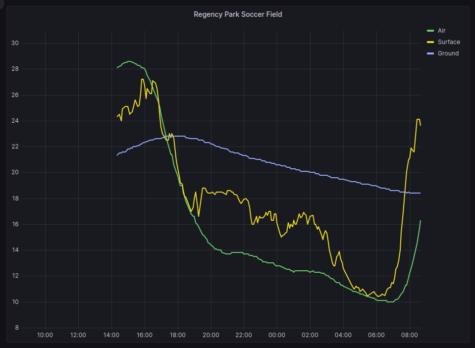
Grafana graph from installed temperature sensors
More details about the project, including the live sensor data, can be found on the project pages:
Note: The LoRaWAN Regional Parameters is set to “Version 1.0.3 Revision A”. This is different to what was found to work with custom developed sensors. It is unclear at this stage what the actual difference is.
The Things Network (TTN) Configuraton
The sensor was easily registered with The Things Network, as the hardware has been pre-configured with a hardware profile from The Things Network Device Repository. This configures the network parameters (as described in the previous section) as well as data formatting functions.
The current Formatter Code returns four data points (Temp_Black, Temp_Red, Temp White, and BatV) and two status values (Work_Mode and ALARM_status).
The code for this uplink data formatting function is as follows:
The data that is then sent through to NodeRED via the MQTT service is a text formatted JSON data structure.
Comments
In previous PAEIoT projects, the decoding of the LoRaWAN uplink data has been done at a later step, in NodeRed. It was done like this for two reasons: 1) The encoded LoRaWAN packets were smaller for transmitting over the network; and 2) Understanding how to decode and process the data could be done separately to anything that TTN does.
Both of these conditions have changed.
In Version 3 of the TTN service, a lot more meta-data about the network is sent with the sensor data, so any advantages of savings made with minimising the size of the internet packet is lost.
As the uplink data formatting code is automatically included by the manucaturer, is available and open-source, provided thatit works, there is no advantage to not using it.
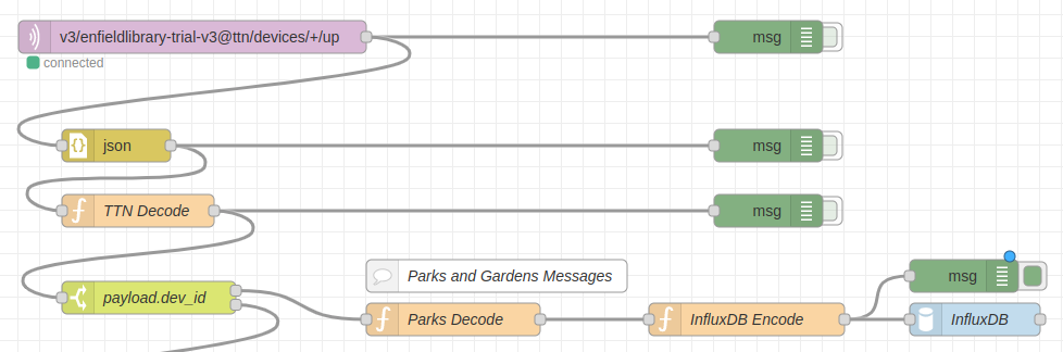
NodeRed and InfluxDB – Data Procesing and Storage
The following flow diagram describes the new path and changes added to support the new temperature sensor.
Specifically, the following changes and details were added.
TTN Decode (minor change)
The “TTN Decode” node now also passes the entire “uplink_message”, rather than just “payload_raw”. This means that the sensor location (longitude, latitude, and elevation) can be set via the registraion of the device in TTN.
payload.dev_id – Switch (New Output Added)
Added switch to separate flow for the Parks and Garden device (dev_id=eui-a840416eb183975f).
Note: When additional sensors are added, this switch node will need to be changed to also select the new sensor.
Parks Decode – Function (New)
This is the main function which pulls out and renames the data. The ‘msg.payload’ contains this data, and ‘msg.meta’ contains tags for the data.
// Parks Decode
// Decode temperature sensing device
// LSN50V2-D23 LORAWAN WATERPROOF TEMPERATURE SENSOR (3 PROBES)

var device_id = msg.payload.dev_id;

var batv       = msg.payload.uplink_message.decoded_payload.BatV;
var temp_black = msg.payload.uplink_message.decoded_payload.Temp_Black;
var temp_red   = msg.payload.uplink_message.decoded_payload.Temp_Red;
var temp_white = msg.payload.uplink_message.decoded_payload.Temp_White;

var latitude  = msg.payload.uplink_message.locations.user.latitude;
var longitude = msg.payload.uplink_message.locations.user.latitude;
var altitude  = msg.payload.uplink_message.locations.user.altitude;

var data = {};
data.batv       = batv;

data.temp_black = temp_black;
data.temp_red   = temp_red;
data.temp_white = temp_white;

data.temp_air     = temp_white;
data.temp_surface = temp_red;
data.temp_ground  = temp_black;

data.latitude   = latitude;
data.longitude  = longitude;
data.altitude   = altitude;

msg.payload = data;
msg.meta = {
    "device_id": device_id,
};

return msg;
InfluxDB Encode – Function (Copied)
This function is the same as prevously used to format the payload prior to sending it to the InfluxDB node (and into the database).
An addtional two queries pull out the data for the surface temperature (temp_surface) and ground temperature (temp_ground) with the filter for the ‘_field’ value being changed respecfully. eg.
The resulting graph (as shown at the top of this post) also has some additional formatting changes (overrides), as pseudo-code:
Where field has name "temp_air", change Display Name to  "Air";
Where field has name "temp_surface", change Display Name to  "Surface";
Where field has name "temp_ground", change Display Name to  "Ground";
Conclusion
The existing PAE-IoT data processing system was modified to allow data from a newly added, commercially available temperature sensor, to be stored, displayed and dynamically updated.
A moderate amount of changes were required due to choices made by the hardware and system vendors. The system design choices that were made were informed by the desire to minimise additional changes if more sensors are added or if the system is extended in other straight forward ways.
The company behind Zerotier have asked for feedback, stories and testimonials from people using their software, and as a more than happy user of their VPN software and network I am pleased to submit this article. I am not being paid for this. I make use of their free tier access, which currently meets my needs, although this may change as my circumstances change and my IoT and home network grows. I have been a very happy user for more than 5 years.
By way of a simple introduction, ZeroTier is a Virtual Private Network (VPN) technology, which enables all your devices to connect to each other via a separate, encrypted and controlled, software defined IP network, supporting both IPV4 and IPv6.
Why is this useful? The Zerotier network provides routers on the Internet which are used to route you packets. The beauty of this is that once you have installed the ZeroTier client on your devices (all major operating systems, including mobile device are supported), and authorised them on your network, they can communicate directly with each other, as if they were on the same local network.
My initial use case was so that I could access my home servers while away from home, particularly from my home wiki from my phone and mobile devices. Installing Zerotier removes the need to add port forwarding on my home router, or install a ‘Demilitarized Zone’ (DMZ) on my home network. Zerotier also allows all services to be available via to VPN, rather than having to open ports for every service or server that I want to access.
Another application is for remote access to remote servers for support services. The security implications need to be discussed with any customers, but having Zerotier installed on the remotely supported computer allows access from any other device which is also on the same Zerotier network. This was used to remotely control a robot at an exhibition and directly interact with the passing public. Like with all network services, the performance depends on the underlying networks.
In a more recent example, there is a plug-in for Zeroier in Home Assistant, which makes it almost effortless to setup secure access to my home management system for all members of the family both inside and outsode the home.
When registering devices on your private network (identified by a 16 digit hexi-decimal number, or 32 bits), you can explicitly set the IP address that devices are allocated, which they get when they authenticate to the network. Even though these IP addresses are private, if you have a register domain, it is possible to create public DNS names for them, which gives you the ability to use your private network in exactly the same way as you may setup a server on the internet itself.
What all this means is that Zerotier allows you to use internet as a ‘first class citizen’, rather than as a second or third, which has what has happened in the past when end users (home and commercial) have been forced to use network work-a-rounds like port forwarding, dynamic DNS websites, OpenVPN and IPSEC/L2TP, other router based solutions, and even manually configured web caching. No configuration change is required to maintain access, provided the end device has reasonably unfiltered access to the internet.
It is definitely worth giving Zerotier a go if you need to access all your devices that are on private networks, or even if you want to access public devices via an encrypted and secured subnet. The free subscription level allows registering up to 25 devices across multiple private networks. Checkout their website at https://www.zerotier.com/
The following is a short list of open source software worth checking out for home automation and IoT. (There will probably be some posts on each of these in the future.)
Usually, a RaspberryPi has been the platform of choice for deploying this software. Due to the current shortage and difficulty of getting RaspberryPis at the moment, Andreas Spiess (the guy with the Swiss accent) has just posted a Youtube video comparing other options using second-hand mini-pcs.
Andreas has also got some older videos introducing IoTstack, linked on the IOTstack website.
Home Assistant
This software for gluing together and managing a lot of the commercially available IoT and Home Automation products available for the home. The software used to connect to these products (called integrations) have been developed by the Home Assistant community and is available as additional plug-in or library which can be installed as required. (See: https://www.home-assistant.io/integrations/)
IoTstack
The IoTstack software is a system for installing, managing and backing up a large number of other software services which may be required (eg. Home Assistant, plus web server, databases, file servers etc.)
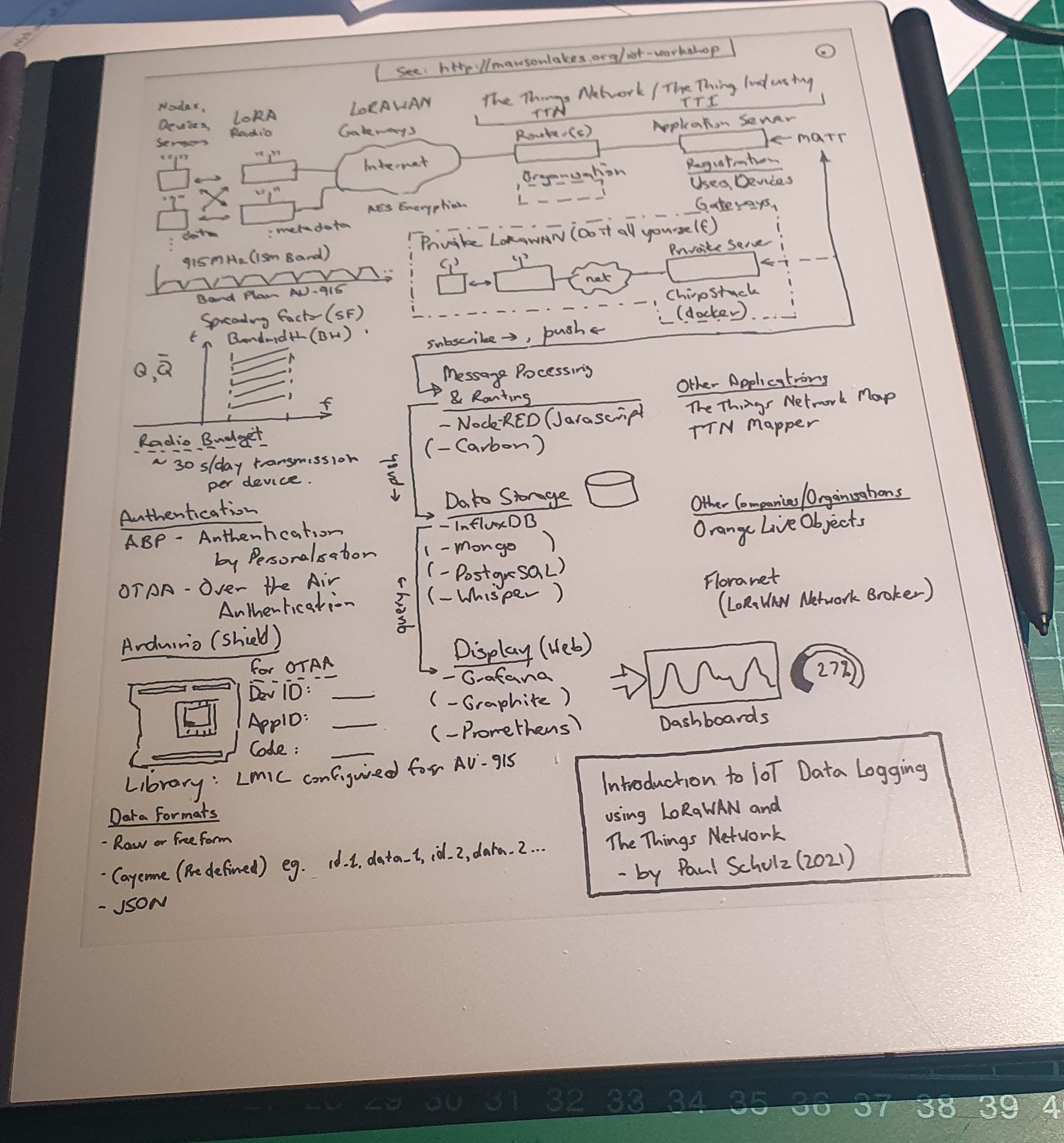
As a birthday present for myself earlier in the year I purchased a “reMarkable 2” e-ink tablet and it’s been awesome. More details about the device below (for those that are interested) but I recently had the chance to use it in a 1-1 meeting covering the PAE IoT Workshop and it worked really well as a paper notebook substitute. Afterwards I was able to go over the details, tidy them up, and rearrange them into a more sensible layout (rather than the original messy stream of consciousness).
Drawing on the reMarkable2
The tablet allows hand written text and drawings to be systematically edited, rearranged and replaced. There is the option on having layers (which I didn”t really use) and showing an underlying templete (lots to choose from) which is a useful guide for keeping everything nicely lined up, and which can be removed afterwards (replaced with the blank one).
The final result can emailed as PDF, PNG, or SVG formatted files, and the result is below.
About IoT Data Logging using LoRaWAN
The following is an example of the path which might be taken by a packet of date, created on a LoRaWAN IoT device, as it makes it’s way from the sensor to be displayed on a web-based dashboard on the Internet.
About the reMarkable2
There is quite a lot to talk about with the reMarkable2 but where is a vary brief summary – it’s a Linux based ARM system, which has Wifi access and drives a e-Ink display with stylus for drawing and input. The display and pen software is closed source, but everything else appears to be Free and Open Source Software. It is possible to SSH into the device from both Wifi and USB-C, with a password that is displayed from the settings menu. If you wanted to you could use that the change any of the software on the device but beware – there be dragons.
reMarkable (the company) currently send out software updates regularly (almost monthly), as these also include new features and tweeks.
There are also third party projects (the reHackable project) which make the tablet even more useful, and support the use of the reMarkable in many more ways than the manufacturer may have intended, including replacing the entire operating system. I have not considered doing this just yet.
In the last part of this blog post series, we look at pulling everything together with InfluxDB and Grafana to store and display outr IoT sensor data.
Tools to Collect and Display Data
In the workshop we are using the following software tools for processing our collected data.
Node-RED – Receive, Process and Push IoT sensor data
InfluxDB – Store the time series of sensor data
Grafana – Display and manipulate the data visualisation
These packages can easily be installed on a Ubuntu system (desktop or laptop) as well as Raspberry Pi Raspian system[1]. In the following I have included the instructions for installing on Ubuntu.
This combination of software will allow data to be displayed is graphs which can be interactively arranged and manipulated, and shared with multiple users on your network.
Node-RED
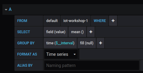
The installation and configuration of Node-RED was discussed in the previous post. An additional module needs to be install to allow Node-RED to send data to InfluxDB.
node-red-contrib-influxdb
InfluxDB
InfluxBD is a time series data store, which is like a database, but different. It is designed for storing and retrieving sequential data which contains timestamps in a more efficient way.
To install
$ sudo apt install influxdb influxdb-client
It uses the default port of 8086.
Before we are able to start storing data, a database needs to be created in InfluxDB, which we can then push our time series data into. This is done from the Linux commad line ($) as follows: First open a influx prompt (>), then create the ‘iot’ database.
$ influx -precision rfc3339
> create database iot
From the influx prompt (>) you can find out more about the available databases
> show databases
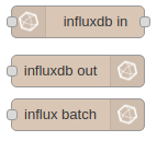
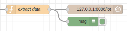
Node-RED can then be configured to push data to this database with the InfluxDB output node, configured as follows.
Configuring InfluxDB node to write to local InfluxDB instance.
A flow can then be configured to pull the data from a Node-RED message and send it to the InfluxDB.
The function used to extract moisture data (analog to digital data in the range 0-1023) is as follows. An additional format check (message starts with “Sensor”) has been added in case some other format is received. The device (device_id) that is reporting the data is specified in the ‘msg.measurement’ field.
var payload = msg.payload.payload_fields.receivedString
var dev_id  = msg.payload.dev_id
var re      = /^Sensor/;
var moisture = 0.0;
if(re.test(payload)){
   payload = payload.substring(10)
   var integer = parseInt(payload,16)
   moisture = integer/1024.0 * 100.0
 }
 msg.measurement = dev_id
 msg.payload = moisture
 return msg;
Grafana
Grafana is a graphing and visualisation package. It can display the information from InfluxDB[3] and display it.
When logging in for the first time, you can use any username and password and you will be then prompted to change it.
Grafana is a very powerful piece of software but does a good job of helping the first time user through the initial setup. It is recommended that you have a read through the Getting Started documentation. The following is a very brief summary of the confugration process, and I have glossed over a lot of the details.
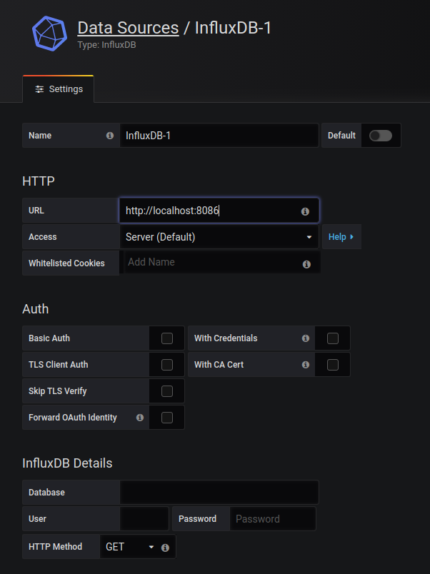
Once you login in, you will then be prompted for a data source. The details to connect to the local InfluxDB is as follows. Click and set the URL to http://localhost:8086 (it may just be displayed in grey which is a trap). There is no username or password needed if InfluxDB is installed as mentioned above.[5]
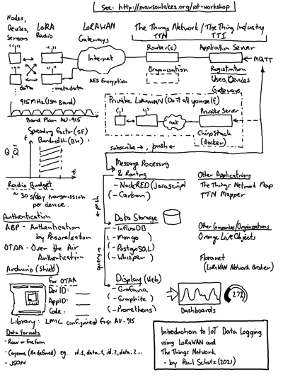
Grafana data query builder.
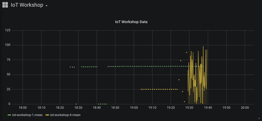
Grafana plots are configured by specifying a data query. In this case we are looking for data from the ‘iot-workshop-1’ device.
The following resulting plot came from defining two data queries for two IoT devices. The second one was configured to generate random data at 10 second intervals for testing purposes.
This series of posts covered the process of building a private IoT platform for collecting and displaying sensor information that uses the Internet to move data about but does not rely on cloud or other 3rd party hosted services other than The Things Network.
There are no ongoing charges or fees with this system, and it is a good introduction to software which can then be adapated for other purposes. Have a look for YouTube videos on how to connect Node-RED to home management systems (Google Assistant or Amazon’s Echo) or create different dashboards with Grafana plugins