At the recent Everything Open Conference, I attended a taik by Vic OIiver on the one handed keyboard called the Quirkey.
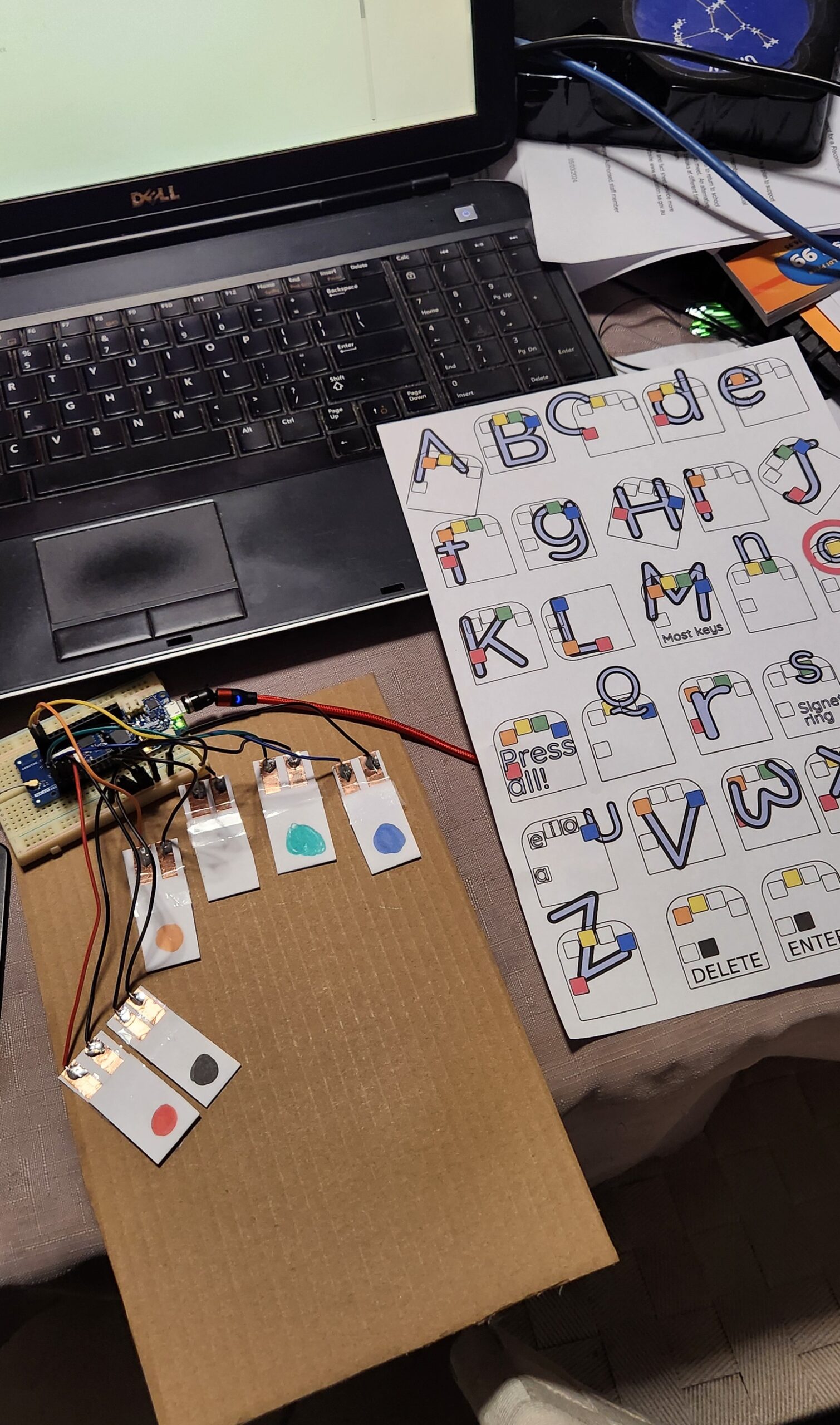
I am attempting to write this blog post using a version of this keyboard I have made out of cardboard, a Arduino MKR 1310 board and some other bits and pieces of stuff that I found lying around the house. (I am going to have to stop here and go back to my regular QWERTY keyboard. I will have another practice later, but at the moment I am finding that I am using the ‘backspace’ more than I would like to.)
While looking into the Arduino code, it occured to me that I had a dev board that would actually work with this code (the Arduino MKR 1310 which had been used in a previous project). In particular, this board supported the HID, and Keyboard and Mouse libraries, which is what allowed this board to appear as (surprise, surprise) a keyboard and mouse device when plugged into a USB port. There ae many naferious project ideas for this sort of technology, but I don’t think that the usefulness has been explored enough.
The Design
This project code takes the corded (multiple symaltanious keypress) inputs, of six buttons, and converts it into regular keyboard input. Vik’s presentation gives more of the backgound, and reasons why knowing how to use one handed keyboard is a good skill to have. In addition, the documentation includes helpful tools to assist in learning this skill, as will as a typing tutor.
So… I have an Arduno board that will do the job (there is a good list of supported boards on the HID Library page), I just need to get some switches.
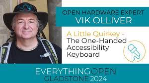
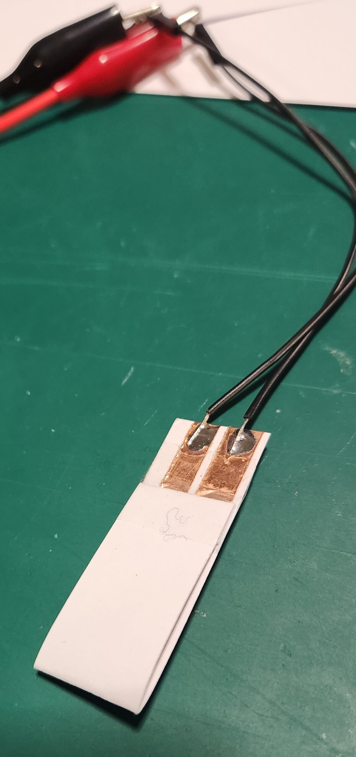
The latest version of the Quirkey keyboards were the result of lots of trial and erro experimentation, and consited of a 3D printed shell with six mechancal switches. My Prusa printer is currently broken and I didn’t have any unused mechanical switches within reach, but I did have some cardboard, copper tape and my trusty soldering iron. So, after some of my own experimentation, we get the following design…
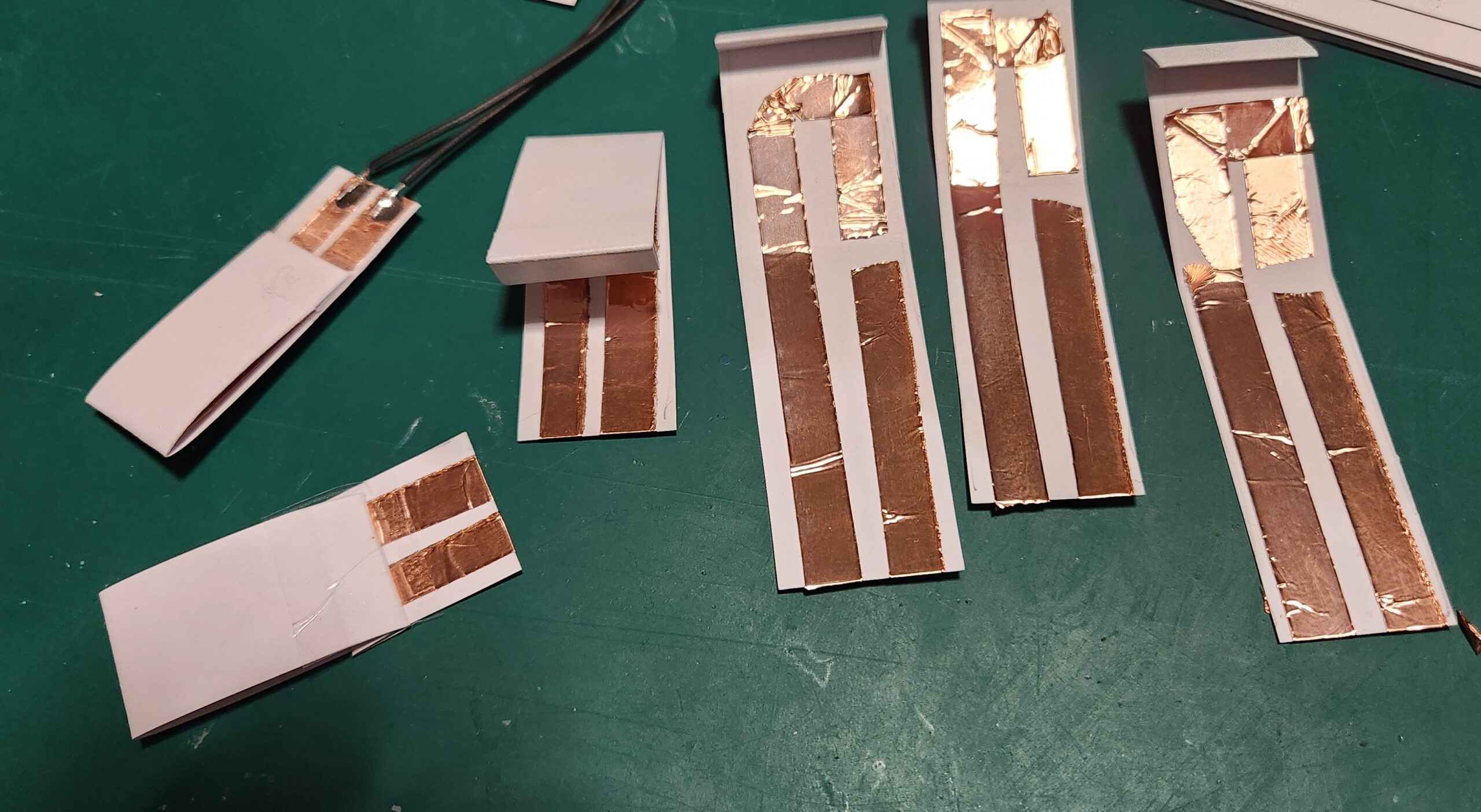
The cardboard switches are stuck down onto a piece of cardboard, wired up to the Arduino MKR 1310 board (any MKR 1000 series boar will work), and programmed with the MicroWriter Ardunio sketch. (Comments in the sketch indicate which pins connect to which switch.)
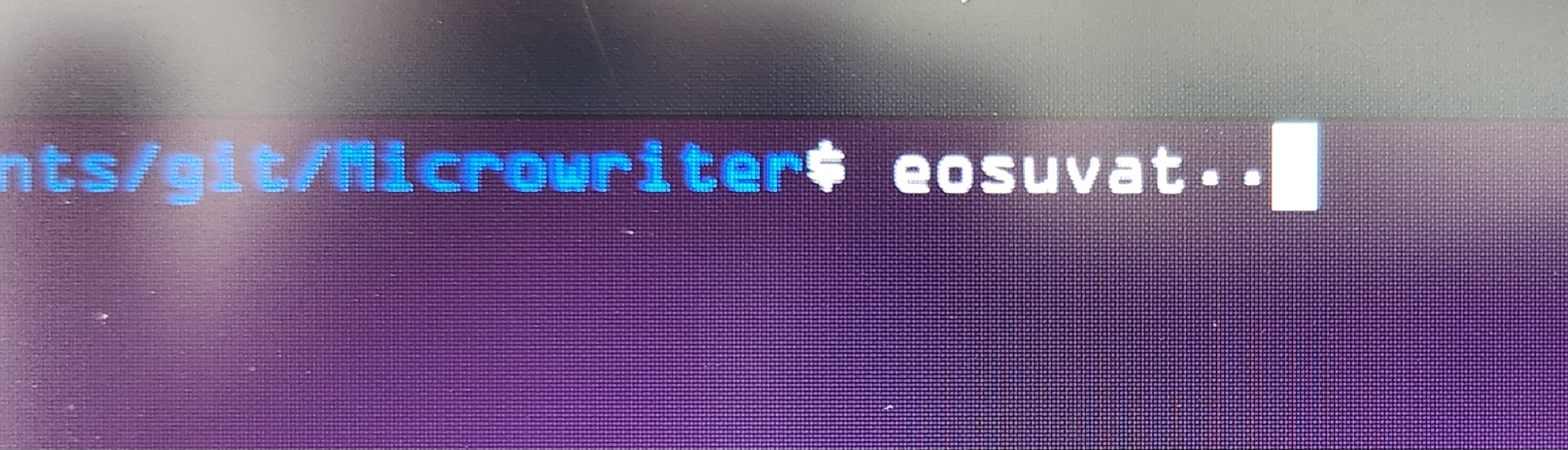
There is a 5 second delay on startup, but the board is now detected as an “Arduino LLC Arduino MKR WAN 1310 Keyboard” and “Arduino LLC Arduino MKR WAN 1310 Mouse”, and works as advertsed.
Conclusion
This is a great cheap-n-cheerful project incorporating a bunch of useful ‘maker’ techniques (soldering, wiring and Ardunio programming) which can be completed resonably quckly.. and at the end you get something useful to play with.
The switches aren’t perfect, but it’s great to have something to use to learn the one handed keyboard technique.
After practicing for a while, for not much more, the paper and copper switches and cardboard can be replaced with something a little more permanent. (A project for the future.)
Open Energy Monitor is a project based in Wales which has developed an energy and environmental monitoring system. They have an energy sensor (the emontx series) which monitors the current in up to four(4) channels, together with the AC voltage, in order to measure the power flowing through electrical circuits.
Current transformers are used, and are placed by clamping around individual wires, allowing the current in the wire to be measured without making any change or direct contact to the existing wiring.
The Open Energy Monitor store are selling their sensors as a kit, and one has been ordered with four current transformers. This will be paired with an already available Arduino UNO to allow for an evaluation of the monitoring software.
We are just after the power measurements for each channel to be reported via a serial connection rather than using their project specific radio (a 433MHz radio link).
All of the code that they are using (with and without the radio link) is available via their forum and github repository.
As we evaluate this system we will be posting the results here.
The Open Energy Monitor also has a good set of documentation on how the units work, how they have been put together, and more on the theory of energy monitoring using current transformers.
Woohoo! A new project, or at the very least some new stuff to learn about. It’s been a while since I learnt about the basics of VLSI design and, in particular the ‘Magic’ chip design software package.
Google have just announced that they are partnering with SkyWater Technology Foundry to produce the “SkyWater Open Source PDK“, to produce a fully open Process Design Kit, for producing VLSI Chips. The 130nm process isn’t the newest, but it is still suitable for a variety of hardware applications.
As part of this collaboration, Google has also announced that they will be sponsoring a chip fabrication run later in the year, completely free for the chosen projects, when all the project code, file and documentation is Free and Open Source.
I’m not sure about you, but I have always loved the thought of producing a custom designed chip, otherwise known as an ASIC (Application Specific Integrated Circuit). There is going to be a whole bunch of things that I am going to have to learn, but being involved in the process of producing something like that will be awesome.
The aim is produce the design with cells provided in the SkyWater PDK. The initial proposal is that there will approximately 10mm^2 apace available (Maybe 3mm x 3mm). The 130nm process would there allow an area of 10,000 x 10,000 transistors ( Very roughly, if the transistors were 300nm in size. 3×10^-3 / (0.3 x 10^-6) = 10 x 10^3 )
Any-ho, this should be a lot of fun… and the Skywater-PDK Slack community has been particularly helpful.
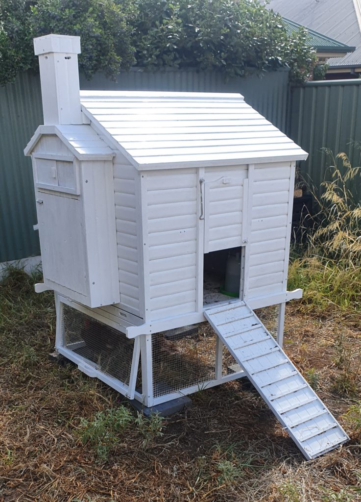
After two years of delay, our household now has a chicken coop and five chickens (Bigbird, Tiny, Rose, Flame and Raptor).
Part of the plan other then getting the birds to produce eggs, eat garden waste, poop and generally scratch around, was to use this opportunity to turn their humble home into a Super Chicken House..
Currently, they need to be shut in and let our every day which which is not much of a chore but still needs to be done. Also, it would be nice to know when there are eggs to be collected, and if they need more water or food. Some temperature monitoring might also be ‘cool’ as well as air quality sensing.
As an acknowledgement to some other great work being done on home automation, the name and logo of the project had been blatantly copied and modified from Jon Oxer’s SuperHouse Automation business. (Does this classify as Fan art?)
Solar Power
I was struggling to find a reasonable cheap way to get power to the SuperCookHouse. I had some sets of solar powered garden fairy lights, several different models to experiment with. They all had internal batteries which charged up during the day and then automatically switched on at night.
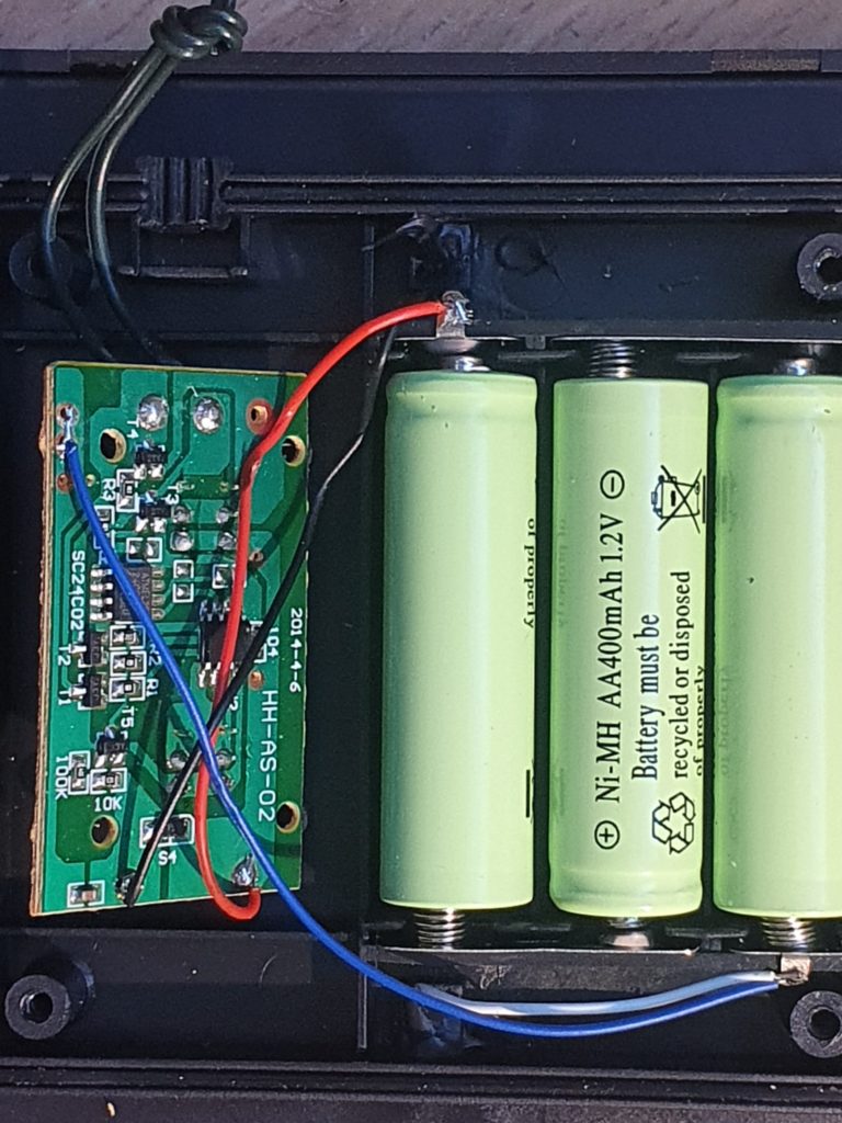
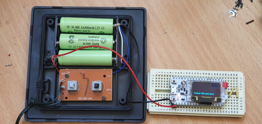
The smaller units had multiple outputs on for their LED’s (three wires) which allowed them to have some interesting twinkle modes. They were cheaper, but they only contained a single Ni-MH battery. The larger unit had three batteries (see image below) but only had a two wire LED output. The cases themselves also had some rubber seals for waterproofing.
Inside connections and batteries of larger Solar Fairly Light unit.
In the larger unit the output from the charged batteries was 4.1V. This proved sufficient to power up a Heltec WiFi LoRa 32 (V2) board which I had at hand. This was connected directly across the batteries.
Connecting a device directly across the batteries.
This connection bypasses the power switch and the flashing circuit of the solar panel board. The batteries should still be able to be charged via the solar panel.
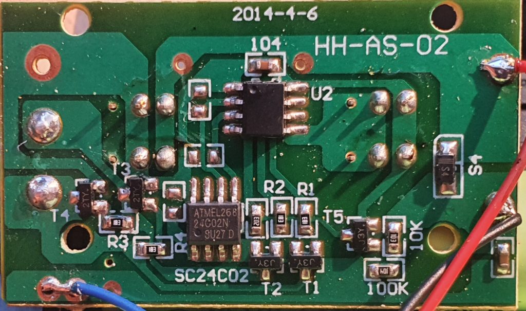
The single-sided controller board.
Briefly looking at the control board, with some hackery, it should be possible to make use of the on/off switch to control external power, but two other modifications would also need to be made;
bypass the flashing circuit
disable the ‘power off’ function when the solar panel is in light.
This work has been left to a time in the future.
Update: The batteries powered the module, as it was without any sensors, for about three hours.
Update 2: It looks like the chip SC24C02 (ATMEL268 24C02N) is an EEPROM 2-wire 2K memory chip (Datasheet). Pins 5 and 6 are the Serial Data (SDA) and Serial Clock Input (SCL) respectfully, which are routed up to pins 2 and 3 on the other (currently unknown) package.
In the previous post we discussed the LoRaWAN network and gave an overview of how it works end to end. This post looks in more detail and describes what’s necessary to get data into the network from individual sensors.
The LoRa Radio and LoRaWAN
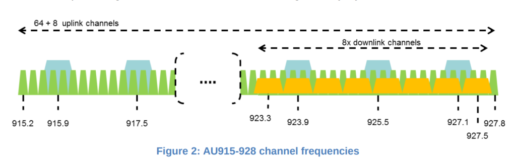
The LoRa radio module transmits in the Industrial , Scientific and Medical (ISM) unlicensed radio band[1]. In Australia (and New Zealand) LoRa transmits between 915-928 MHz[2]. For uploading data, the band is divided into 64 narrow bandwidth channels of 125 kHz, with an additional 8 overlapping broader channels of 500 kHz.
The data is encoded using a chirp signal. The rate that this frequency changes is defined by a ‘spreading factor’ (SF), and a doubling of the spreading factor approximately doubles the amount of time it take to transmit data[3].
LoRaWAN Channel Allocation for Australia and New Zealand
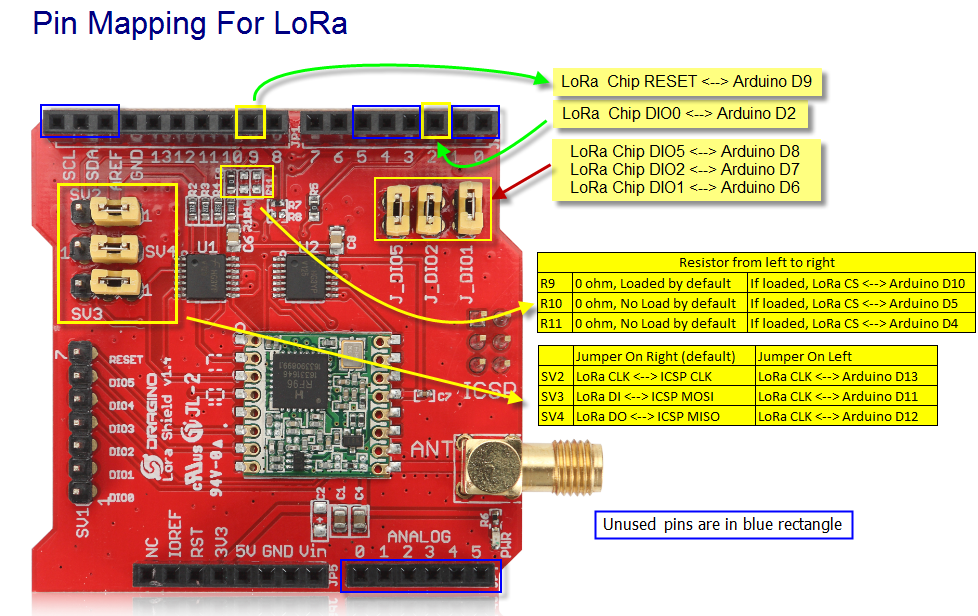
To use LoRa and LoRaWAN we are using the following LoRaWAN Arduino Shield available from the local suppliers. It is supplied to transmit and receive in the 915 MHz. As purchased the jumpers were not set, and needed to be installed as indicated in the picture below.
When developing hardware, it is only possible to use digital input/outputs 3,4 and 5 (3 lines). Digital IO 0 and 1 are used by serial IO and interfere with programmng. The digital lines D11-13 are used to control the LoRa radio.
The available Arduino pins for projects are
D3-5 (3 digital lines) – Can be sed for Digital IO
D0-1 (2 digital lines) – Can be used for Digital IO but interferes with in circuit programming. Needs to be disconnected first.
A0-5 – Canbe used for Analog Input or Digital IO
SCL,SDA – Can be used for Digital IO and Analog In on Arduni Uno.
AREF – Used as analog reference voltage
GND – Ground
Software
Arduino Library for LoRaWAN (LMIC)
The Arduino LMIC library that we are using is being maintained by Thomas Laurenson and can be found on Github[1]. The original LMIC Library was written by IBM and has been ported for use with the Arduino board.
Once downloaded and installed in the Ardiuino IDE library directory[2], the software needs to be configured to use the Australian frequency plan which is done by editing the file ‘project_config/lmic_project_config.h’. For some reason the Australian configuration is called CFG_au921.
Notes: [1] Github: https://github.com/thomaslaurenson/arduino-lmic [2] When unzipping the software, there may be duplicated recursive top level directory names (eg. arduino-lmic/arduino-lmic). Ensure that only one level is copied into Arduino library folder.
Example Arduino Sketch
An example Arduino sketch also available from the GitHub repository, which can be used to connect to the LoRaWAN network. See arduino-lmic/examples/ttn-otaa-dragino-lorashield-au915[1].
When connecting to the LoRaWAN network there are two authentication methods “Authtication by Personalisation” (ABP) and “Over the Air Authentication” (OTAA). While it is a little more complicated, OTAA is preferred as it allows the network more control over the authentication process, but requires two-way communication with the end-node. ABP does not require the end-node to receive data from the network but the network needs to know when the end-node is ever reset[2].
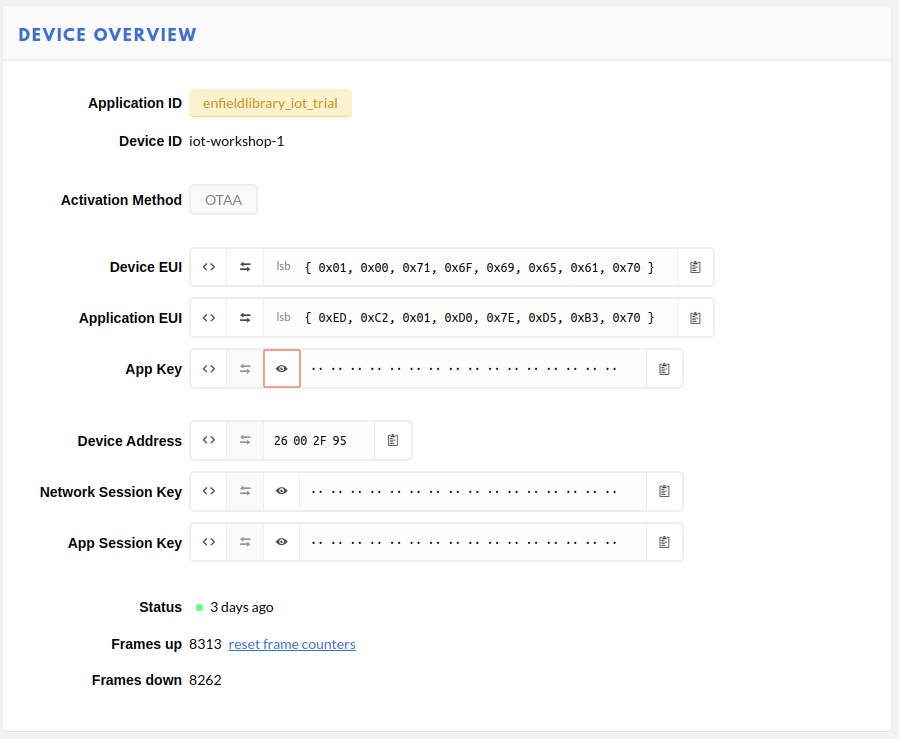
For OTAA, there are three pieces of data that need to be copied into the sketch, and are obtained from The Things Network console[3].
Device EUI (DEVEUI) – This is the unique identifier for this device on the network. This can be changed. This needs to be used in the sketch in Least Significant Byte (lsb) order.
Application EUI – This is the application identifier, and is unique across the LoRAWAN network. This needs to be used in the sketch in Least Significant Byte (lsb) order.
Application Key – This is an initial encryption key shared between the Node and Application. It can be changed. This needs to be used in sketch in Most Significant Byte (msb) order.
The webpage tries to make this as easy as possible by allowing you to adjust the formatting and the copy to clipboard button.
Device confiuration parameters in The Things Network
These details are copied into the Arduino sketch in the FILLMEIN locations as shown below.
// This EUI must be in little-endian format, so least-significant-byte
// first. When copying an EUI from ttnctl output, this means to reverse
// the bytes. For TTN issued EUIs the last bytes should be 0xD5, 0xB3,
// 0x70.
static const u1_t PROGMEM APPEUI[8]= { FILLMEIN };
void os_getArtEui (u1_t* buf) { memcpy_P(buf, APPEUI, 8);}

// This should also be in little endian format, see above.
static const u1_t PROGMEM DEVEUI[8]= { FILLMEIN };
void os_getDevEui (u1_t* buf) { memcpy_P(buf, DEVEUI, 8);

// This key should be in big endian format (or, since it is not really a
// number but a block of memory, endianness does not really apply). In
// practice, a key taken from the TTN console can be copied as-is.
static const u1_t PROGMEM APPKEY[16] = { FILLMEIN };
void os_getDevKey (u1_t* buf) {  memcpy_P(buf, APPKEY, 16);}
In the sketch, the following line can also be changed.
static uint8_t mydata[] = "OTAA"
This is the data that is going to transmitted over the network. This short string can be edited to something more meaningful. The sketch can then be compiled and installed, and if a LoRaWAN Gateway is within range, transmitted data will start to be collected by The Things Network Application.
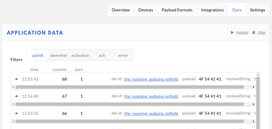
The transmitted packet data will appear under the Application Data on The Things Network.
Data packets being received from an IoT device via LoRaWAN
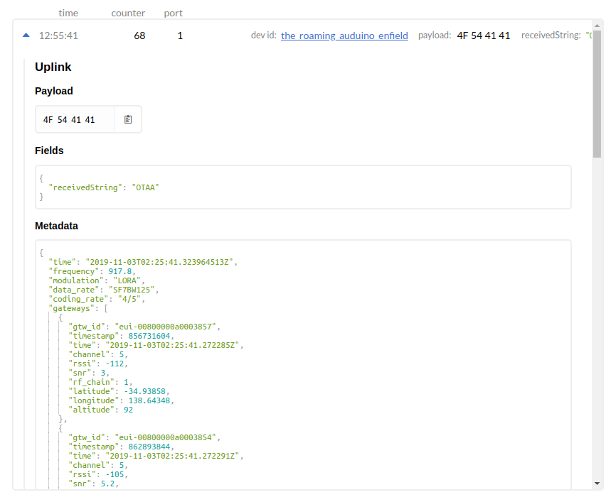
The information includes the data transmitted by the IoT device and metadata from the network about the transmission. Expanding the packet entry shows this detail.
In the case above, to assist with debugging a custom Payload Format decoder has been added which converts the bytes to a string with can be seen in the ‘receivedString’ field[1].
// Decode an uplink message from a buffer
// (array) of bytes to an object of fields.
function Decoder(bytes, port) {
   // var decoded = {};
   // if (port === 1) decoded.led = bytes[0];
   // return decoded;

   // Decode plain text; for testing only
   return {
       receivedString: String.fromCharCode.apply(null, bytes)
   };
 }
The raw transmitted data can be seen in the Payload.
The metadata fields show the frequency used (917.8 MHz), the datarate (SF7BW125 – Spreading Factor 7, Bandwidth 125 kHz) and the gateways which heard the transmission and their details.
The next step will be to look at how to make use of the collected data. NodeRed is a software package will be used to process and manipulate the data as it is received.
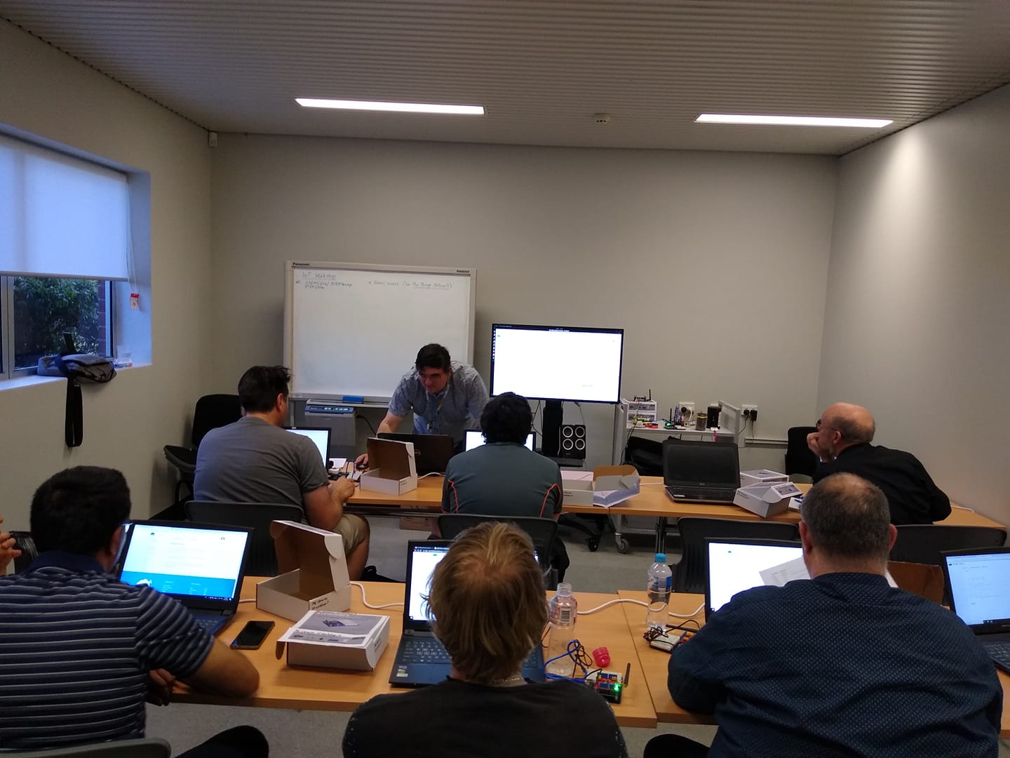
On Thursday (24 Oct 2019) we started running the first session of a new IoT workshop, being held at the local libray (Enfield Branch of the Port Adelaide Enfield Council). This workshop aims to be an introduction to creating sensors and nodes for the LoRaWAN IoT network, using The Things Network website.
This first sesssion (of four) was a whirlwind dump of details which we will unpack and work on through the remainder of the sessions, with hands on electroncs and programming.
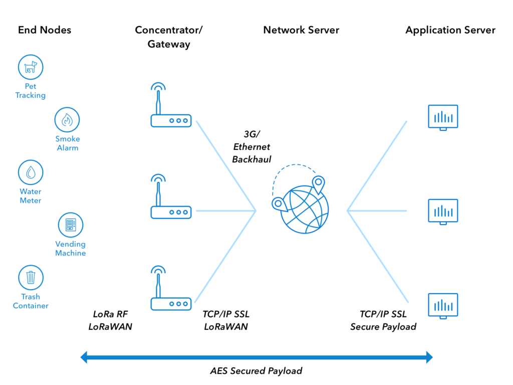
We went though the architecture of the system and got everyone to create an account on The Things Network, and set them up so that they could see the IoT data that was being transmitted over the network.
Architecture of LoRAWAN Network (from The Things Network)
Technolgy discussed..
A quick summary of the various bits-n-pieces that are being used follows.
LoRa
The radio technology that is used by sensors for ‘Long Range’, low bandwidth communication. These radios may be programmed to be used in either point-to-point or point-to-gateway (LoRaWAN) mode, configurable with software. They use the unlicensed ISM radio bands, 911MHz in Australia.
The radio network and infrastructure used to collect sensor data, via publically accessible gateways.
Arduino
A microprocessor board and programming tools, which use the Atmel (and other) microprocessor. The original aim was to create a programming system which was easy to use for hobbyists and members of the maker community. Arduino microprocessor boards can be used with a LoRa radio to create sensors which can transmit data via LoRAWAN and the internet to be collected and used by other applications. https://www.arduino.cc/
Arduino Shield
This is additional hardware that has been designed to plug directly into an Arduino board and allow it to be easy to use.
Arduino IDE
The Interactive Development Environment (IDE) used to program an Arduino microprocessor board. It is available as a downloadable Java program, and as a web based application. The software is available from the Arduino website.
Arduino Libraries
Additional software packages which can be installed to extend Arduino programs. For example, the LMIC library is used to allow our Arduino programs to use the LoRaWAN radio shield.
Libraries can be downloaded from within the Arduino IDE, or downloaded and installed manually.
LoRaWAN Sensor Node
A device which collects data and transmits to the LoRaWAN network. It uses a LoRa radio. They need to be registered and authenticated with the LoRaWAN network to transmit correctly.
LoRaWAN Gateway
A device which listens for LoRaWAN radio transmissions from nodes in its area and forwards them to the servers on the LoRaWAN network. They need to be connected to the internet and be registered to operate.
The Things Network
A free website (registration required) which allows access to data collected by LoRaWAN sensors. It is used to register LoRaWAN gateways on the network, and create LoRaWAN applications.
MQ Telemetry Transport. This is the communication software and protocol used to allow sensor data to be distributed and used once it has been collected by The Things Network.
NodeRed
A web server program, which can be installed on a home computer or server (or Raspberry Pi) which can collect and use sensor data collected. It uses MQTT to access sensor data.
NodeRed is an automation environment and is useful for a lot more than collecting and displaying our IoT data. See the website for more details.