Tag Archives: RaspberryPi

Creating a Storybot

Testing Storybot output on a regular USB printer

Work has begun to create a robot for dispensing short stories at the touch of a button for Writers Week in 2020. The Storybot will be located in one of the Port Adelaide Enfield libraries and will print from it’s collection of pre-curated stories onto paper via a thermal printer for library patrons to take away with them.

Design

The initial design of the Storybot uses the following parts:

  • Raspberry Pi 4, with MicroSD card
  • Thermal Receipt Printer, USB (24V)
  • Button, resistor (220 Ohm) and connecting wire
  • Power supply (for Rasperry Pi and Printer)
  • Enclosure and stand

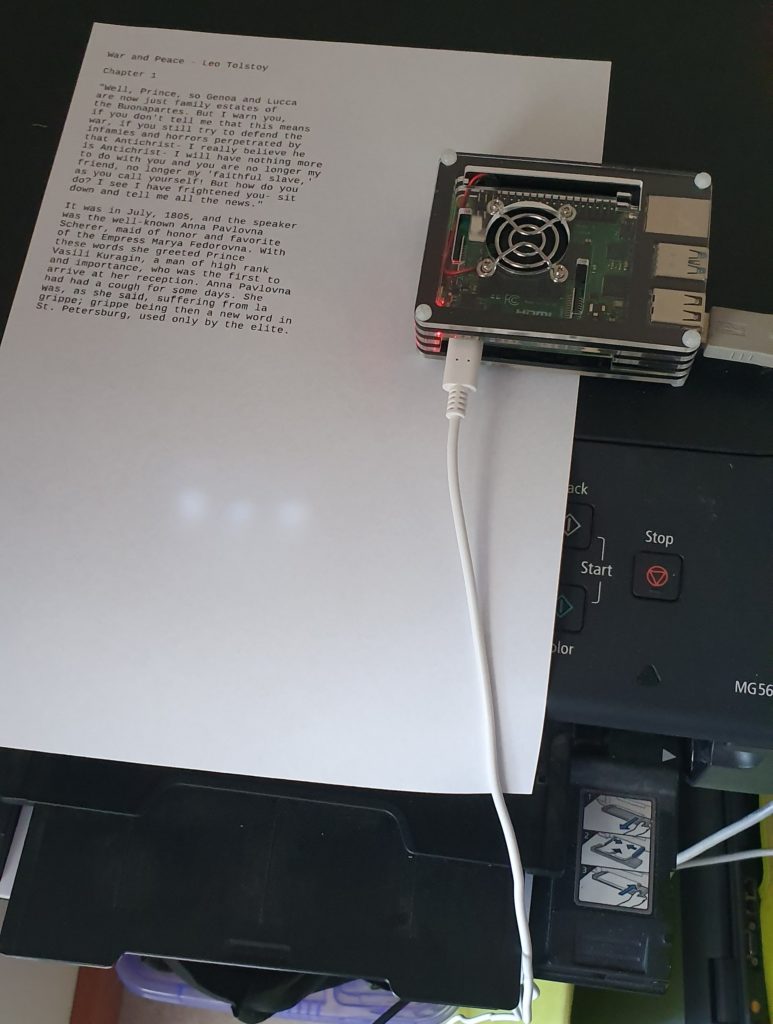
Intial print testing was done with a regular Canon USB Pixma printer.

Software

A repository of the code created for the Storybot can be found on GitHub. This repository ‘storybot’ is cloned directly into a subdirectory of the ‘pi’ user (in our case we are using ‘Document/git’).

The Raspberry Pi used has the most recent Raspbian installed which has been updated to the latest packages.

In addition, the CUPS Printing package has been installed, which allows Raspberry Pi to print to any of the supported printers including the receipt format thermal printer. This printer prints 40 column per row with a fixed width.

A quick solution[1] for selecting a random story used the ‘fortune‘[2] package.

Stories are copied to a directory on the Raspberry Pi as individual ASCII text files. Some example files have been created for testing purposes[3]. A global data file and index is created from these files, while also reformatting them for a 40 character line length. Fortune reads these files, and will extract a story and print it.

Story management is driven by a global Makefile with the following targets:

    make help    - this message (default)
make story - display a story
make prepare - compile the stories into data file
(This will be run automatically, if required.)
make list - list story files
make clean - reset system by removing generated files
make status - display system status

This system allows dependencies to be managed, so that ‘make prepare’ would be run if it is required and hasn’t yet been run, before ‘make story’. This allows new story uploads to be done even while the system may be printing.

Printing is done by sending (piping) the story output directly to the default printer with

    make story | lpr
Adding a button

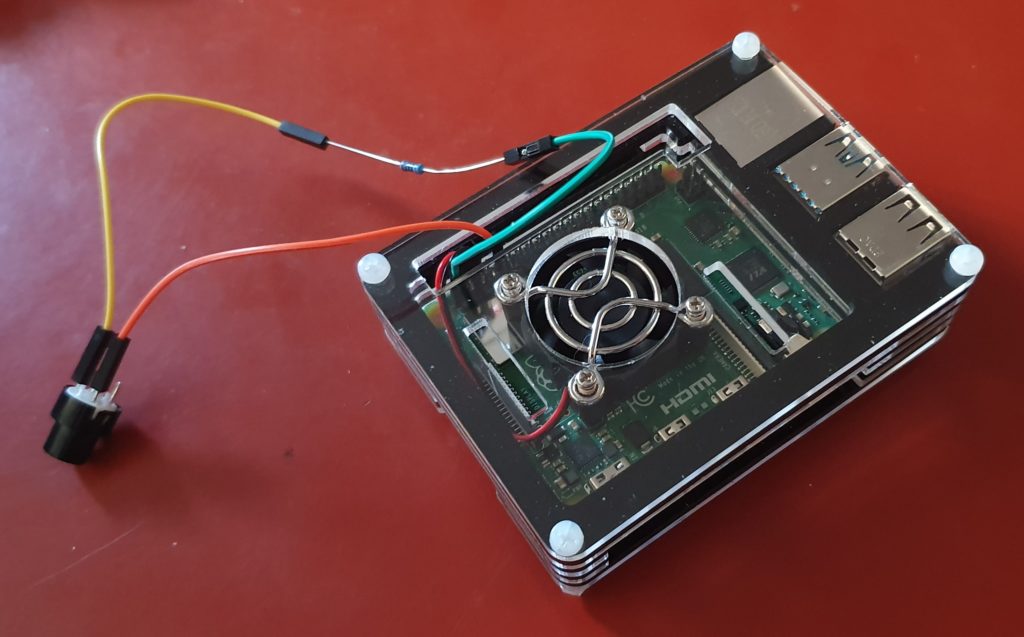
To detect a button press, where a button has been wired up to a GPIO pin, there are several options available. These still need to be investigated, but they include:  Node-RED, WiringPi (C code and used in a previous project) or RPi.GPIO (Python)

  • Node-RED: This is a large-ish application, but it works well and does not require any addional configuration on system start-up and shut-down.
  • WiringPi: This C/C++library is useful for creating lightweight binary programs, but requires additional configuration to enable the created files to restart on reboot/startup. It is no longer being activity supported by it’s developer, but is open source software.
  • RPi.GPIO: Python library that together with Python makes writing scripts that interact with the GPIO on the RasberryPi very easy.

Each of these approaches will need to take care of button bounce/noisy inputs, and stop multiple press events happening in a short period. Some hardware conditioning may also be necessary.

Notes:
[1] Very quick. There are no options for recording any statistics about which stories are printed, or when, which might be a useful thing to record and report on.
[2] The fortune package has a very long history, originally appearing in very early editions of UNIX operating systems.
[3] Stories fro testing were created from the inital paragraphs from “The Princess Bride”, “War and Peace” and “A Tale of Two Cities”.

Building a Junk Rover (Part 2)

Introduction

The Junkbote Rover

In the last article, we posted about how the Junkbot rover was built and what went into its initial construction. Since that post was written, the robot has been completed and it is now does everything it was designed to do and a little bit more.

This article will describe what has been added and changed. It then also discusses what additional things could be added or changed in the future, or included in any new robot projects. (Watch this space!)

The Junkbot appeared at the recent Science Alive 2019, at the Port Adelaide Enfield diplay, and while there, was driven around remotely, making friends with the visitors.

Completing the Build

There have been some minor changes and additionss to the robot as seen in the picture above. Cosmetically, the green button in the middle of his ‘head’ has been replaced with a red numerical display that shows the battery voltage. The black speakers (USB) below this have been replace with a larger box containing USB powered/amplified speakers that take their audio from a line-in (line-out from the Raspberry Pi computer) which are louder and are more reliable. The original USB based audio speakers would periodically just stop working.

On the side of the top grey box, a pair of sero motors have been added, one on each side. The customer will be able to add what every they want to these. These were wired to the Raspberry Pi PWN board, and can be controlled to go up and down independantly.

Driving the Robot

As mentioned in the previous article, the computer controlling the robot is a Raspberry Pi 3, running with a custom Python program which uses keybaord input to then drive the various motors and servos on the robot. The operating system bering used is Raspbian, which has a graphical desktop, similar to MS Windows or Apple iOS, but instead of displaying oit on a screen, can be shown on another computer on the network, via a program called VNC. This easily allows someone sitting at a computer screen, possibly at a long remote distance, to see what the rovers computer sees, and control it in exactly the same way as if they were sitting next to it (as if it had a screen, keyboard and mouse attached).

When running the driving software, pressing keys on the keyboard (‘w’,’a’,’s’ and ‘d’) will make the robot drive forward, left, backwards, and right. Other keys will make it move its servos up and down, as well as completely stop.

Webcam software displays the camera image, so the driver can see where they are going.

In addition, by using some standard video conferencing software (Google) , the robots speakers and microphone can be used to hold conversations with people near the rover. Voice changing software on the call add additonal interest, giving the robot even more personality.

Improvements, Upgrades and Future Plans

The rover uses the Raspberry Pi 3 computer. An immediate improvement to performance, if required, is to upgrade this to a Raspberry Pi 4, with larger memory. The board can be resonably easily swapped out, and running the new board from the existing SDcard.

The Raspbian operating system, which is based on Debian, made the task of developing the driving software, and integrating it with other standard software packages (audio, video, remote desktop etc) very easy to do. Little, if any, changes neede dto be made to get the various software packages to work together. It almost felt like cheating. If there is any other requirement for the rover (eg. adding USB Scanner) then adding this aught to be straight forward, particularly it already exists on a general purpose linux desktop system. Raspian has also been configured to work on the small Raspberry Pi, which avoids a lot of possible finiky problems with system settings that may not be suitable on a resource constrained system.

Much of the other robot software systems out there are specifically written with particular robot hardware platforms in mind, and run on predefined operating systems. An example of a Open Source option is ROS (Robot Operating System and ROS2), but these only run on particular versions of Ubuntu. It would be interesting to use ROS2, as it allows greater flexibility in how the robot can be operated, including tracking and autonomous driving modes, as well as a bunch of other robot options. The learning curve is also quite steep.

Os menioned, the driving softwareis keyboard based. It could be replaced with a graphical tool, maybe also written in Python (Qt4Py). The keyboard events could still be captured and used, but the display could be use to provide more information and create an easier way to operate the rover, An example of this migh tbe a more intuative display of the of motor tuning parameters used to drive of the motors. Getting the rover to drive straight was always little bit tricky.

Along the lines of hardware improvements and additional sensors, shaft rotation sensors could be added to the wheels to get better motion/position sensing, or accellerometer and gyro sensors. It is possible to add an Xbox Kinect sensor bar as a distance sensing camera, which would be useful if driving in an area where people might be moving.

Building a Junk Rover

Another project for 2019! I am helping build robot rover with a “junk” theme (eg.make from e-waste) for use in school education program about recycling and reuse of electronic waste.

This is being done as part of my involvement as a volunteer with Port Adelaide Enfield Libraries and their STEM Program.

Robert has built the hardware which consists of a chassis made of old computer boards. The eyes are recycled IP security cameras which no longer work. The video is coming from a webcam, and the mouth is the usual set of stereo speakers sold for use with the Raspberry Pi computer. To control the motors and other moving parts, the Junkbot uses a small Raspberry Pi computer and a 16 Channel PWM PiHat from Core Electronics.

All of this work has been done with the aim of releasing everything under Free and Open licenses (both hardware designs and software). It would be great if the project reached a point where we not only made something useful for the STEM program but that others could use as a base for their own projects. (If any of this is useful to you, please let me know.)

All of the code from this project is available at Github.

The robot is running ‘Raspbian’ on the Raspberry Pi with the Python Libraries from Core Electronics to enable the wheel motors ans servos to be crontrolled via Pulse Width Modulation (PWM) and the attached PWM board.

For better or worse it was decided to create a keyboard control interface to drive the robot. The desktop screen of the Raspberry Pi is exported over Wifi and the internet via VNC, which can be accessed via VNCviewer. Using keyboard controls we can drive the robot motors, which also allowed us to then tune it’s operation.

As an initial observation, smooth driving operation of the robot might sound like a good idea but it appears as though with remote camera access, control is better if the robot makes small moves, allowing the video display to catch up.

Tuning, modifications and upgrades continue.

More about the construction

From Robert Hart on the electronics…

Inside the head of the Junkbot

The robot will run on a S3 Lipo (on the left in the picture above). Its nominal voltage of 11.1V (3.70V*3 cells) and a fully charged 3S pack is 12.60V and a fully discharged 3S pack is 9.00V. I have incorporated two 5V buck (voltage) convertors: 5A for the Raspberry Pi and 3A for the Servo Hat. The two motors are driven using two Electronic Speed Controllers (ESC)

Waterproof Electronic Speed Controller

The ESCs have had the fans are removed and the on/off switchs have been removed and shorted. The servo lead has also had its postive wire open circuited so not to feed its 5V rail back into the Servo hat.

The Rasperry Pi and Servo Hat can be seen to the right of the box. The ESC’s are above that, with the two voltage converters at the bottom.

LoRaWAN Node and Gateway

LoRaWAN Node and Gateway

With assistance of the STEM Education resources from the Port Adelaide Enfield Libraries, I have been investigating LoRaWAN devices, how to build them and how they can be used.

There is more investigation to be done, but the node shown in the picture above is able to do the following:

  • Connect and Authenticate to a LoRaWAN network (The Things Network) via Over The Air Authentication (OTAA); and
  • Send data (Uplink) and Receive data (Downlink) via the LoRaWAN Gateway(s). (Downlink data is queued, and is received in a window after Uplink data has been received by the network. This reduces power usage in the node.)

The Node used was the Gragino Arduino Shield (or clone from duinotech)

The Gateway is the uGateway LoRaWAN from Core Electronics. Having a local gateway is not necessary if there is another one in the neighbourhood, within range of your node. There are currently no nodes in my area so an internal gateway was required for development and testing. The other option was to take the Node for a drive in the car after a development session, but this made debugging very tiresom, very quickly.

There are a couple of other useful tools worth mentioning.

TTN Mapper is an Android application that will monitor your device on your smart phone, via The Things Network. It then used your phones GPS to log the position of your device. The result is that you can map the coverage of nearby gateways by using your LoRaWAN node and phone in a similar way to how Wireless Access points used to be mapped (WarDriving). This is useful for knowing where your nodes have TTN access, and where additional gateways might be required.