Author Archives: paul

About paul

Paul is the Owner and Creator of MawsonLakes.Org.

IoT Workshop

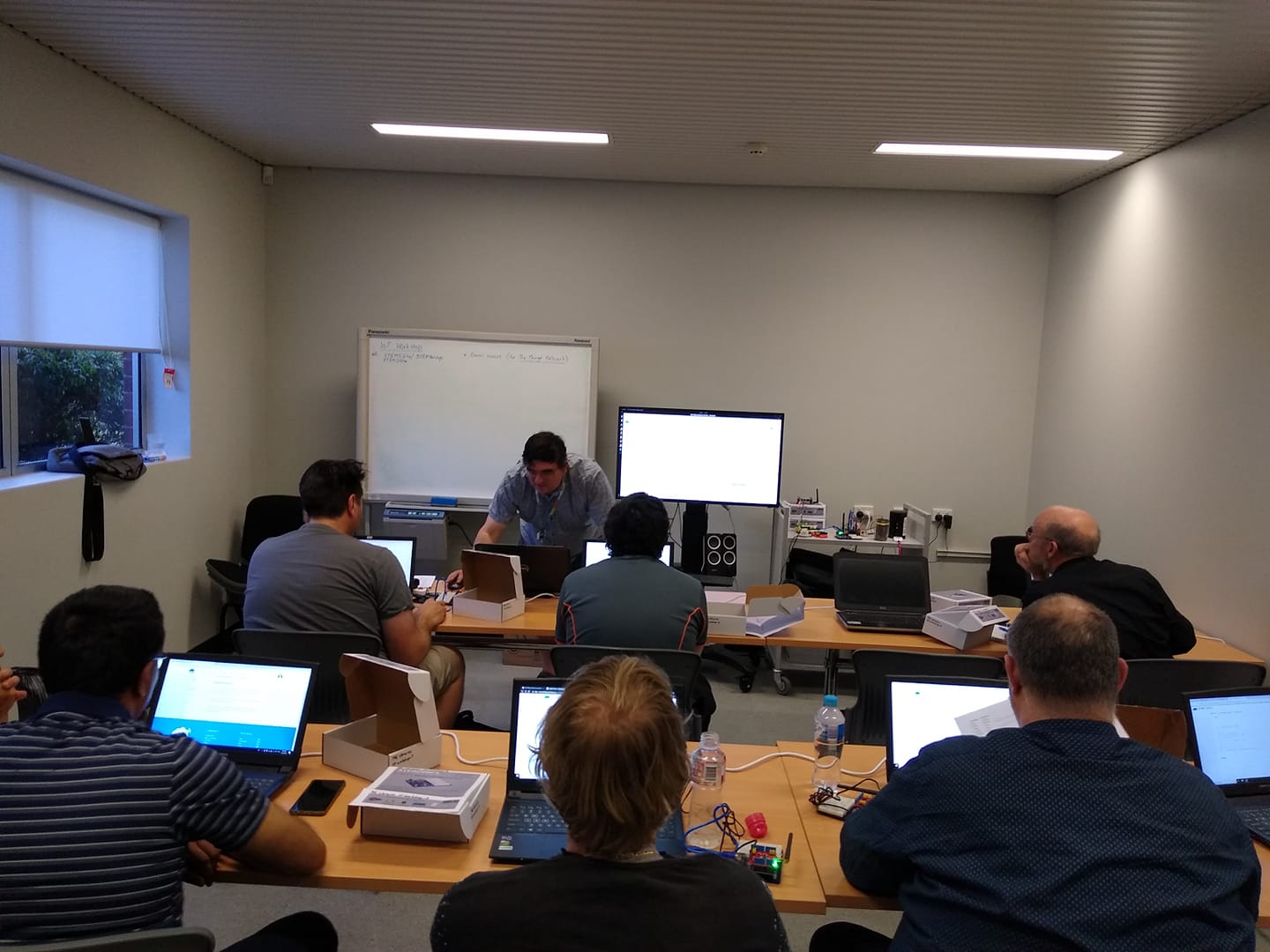
On Thursday (24 Oct 2019) we started running the first session of a new IoT workshop, being held at the local libray (Enfield Branch of the Port Adelaide Enfield Council). This workshop aims to be an introduction to creating sensors and nodes for the LoRaWAN IoT network, using The Things Network website.

This first sesssion (of four) was a whirlwind dump of details which we will unpack and work on through the remainder of the sessions, with hands on electroncs and programming.

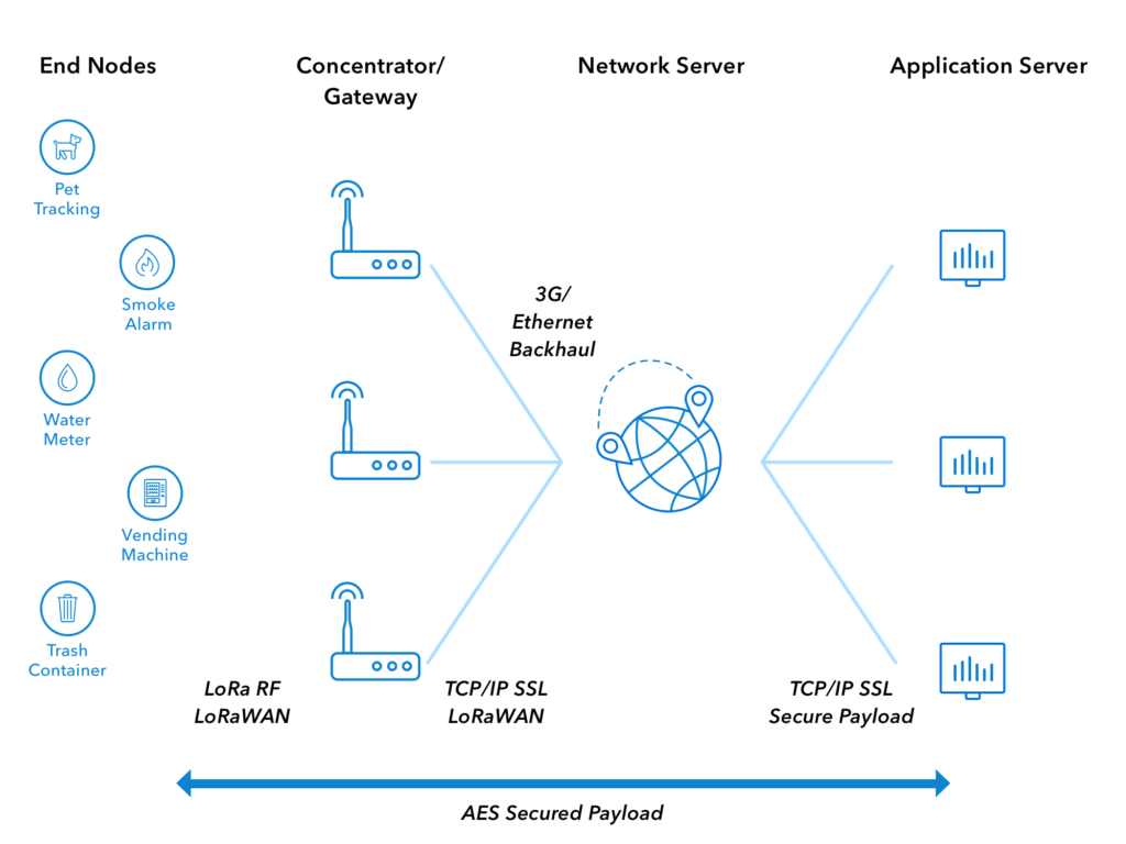
We went though the architecture of the system and got everyone to create an account on The Things Network, and set them up so that they could see the IoT data that was being transmitted over the network.

Architecture of LoRAWAN Network (from The Things Network)

Technolgy discussed..

A quick summary of the various bits-n-pieces that are being used follows.

LoRa

The radio technology that is used by sensors for ‘Long Range’, low bandwidth communication. These radios may be programmed to be used in either point-to-point or point-to-gateway (LoRaWAN) mode, configurable with software. They use the unlicensed ISM radio bands, 911MHz in Australia.

https://en.wikipedia.org/wiki/LoRa

LoRaWAN

The radio network and infrastructure used to collect sensor data, via publically accessible gateways.

Arduino

A microprocessor board and programming tools, which use the Atmel (and other) microprocessor. The original aim was to create a programming system which was easy to use for hobbyists and members of the maker community. Arduino microprocessor boards can be used with a LoRa radio to create sensors which can transmit data via LoRAWAN and the internet to be collected and used by other applications. https://www.arduino.cc/

Arduino Shield

This is additional hardware that has been designed to plug directly into an Arduino board and allow it to be easy to use.

Arduino IDE

The Interactive Development Environment (IDE) used to program an Arduino microprocessor board. It is available as a downloadable Java program, and as a web based application. The software is available from the Arduino website.

Arduino Libraries

Additional software packages which can be installed to extend Arduino programs. For example, the LMIC library is used to allow our Arduino programs to use the LoRaWAN radio shield.  

Libraries can be downloaded from within the Arduino IDE, or downloaded and installed manually.
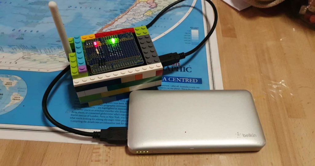
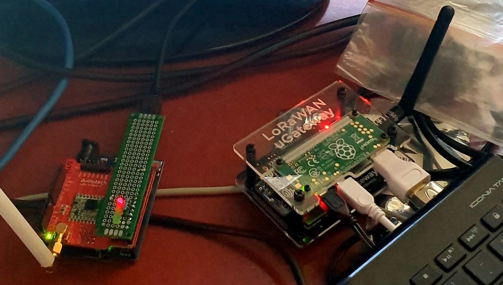
LoRaWAN Sensor Node

A device which collects data and transmits to the LoRaWAN network. It uses a LoRa radio. They need to be registered and authenticated with the LoRaWAN network to transmit correctly.

LoRaWAN Gateway

A device which listens for LoRaWAN radio transmissions from nodes in its area and forwards them to the servers on the LoRaWAN network. They need to be connected to the internet and be registered to operate.

The Things Network

A free website (registration required) which allows access to data collected by LoRaWAN sensors. It is used to register LoRaWAN gateways on the network, and create LoRaWAN applications.

https://www.thethingsnetwork.org/

MQTT

MQ Telemetry Transport. This is the communication software and protocol  used to allow sensor data to be distributed and used once it has been collected by The Things Network.

NodeRed

A web server program, which can be installed on a home computer or server (or Raspberry Pi) which can collect and use sensor data collected. It uses MQTT to access sensor data.

NodeRed is an automation environment and is useful for a lot more than collecting and displaying our IoT data. See the website for more details.

https://nodered.org/

TTNmapper

Mobile application which can be used to map LoRaWAN coverage.  https://ttnmapper.org/
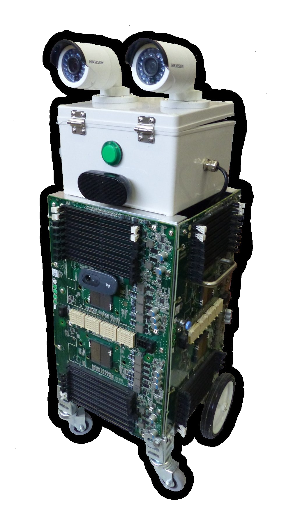
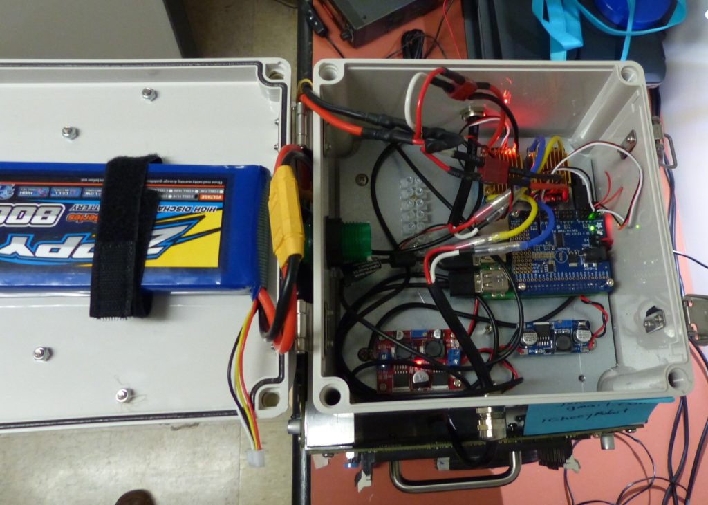
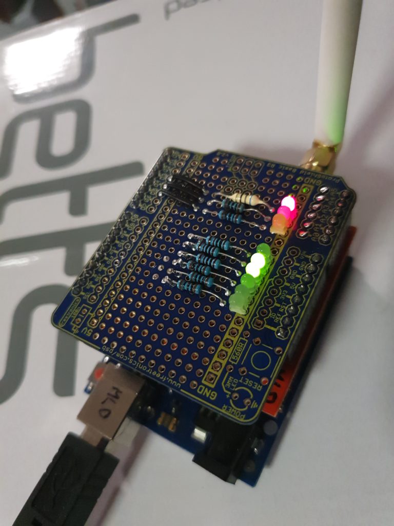
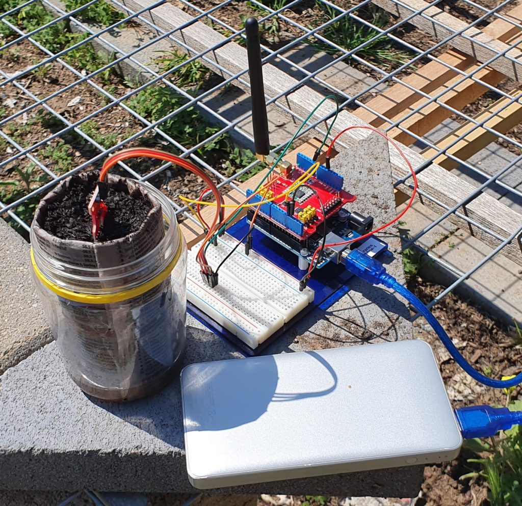
Sensor/Node Example

The following are some example of the sensors that will be built in the workshop.
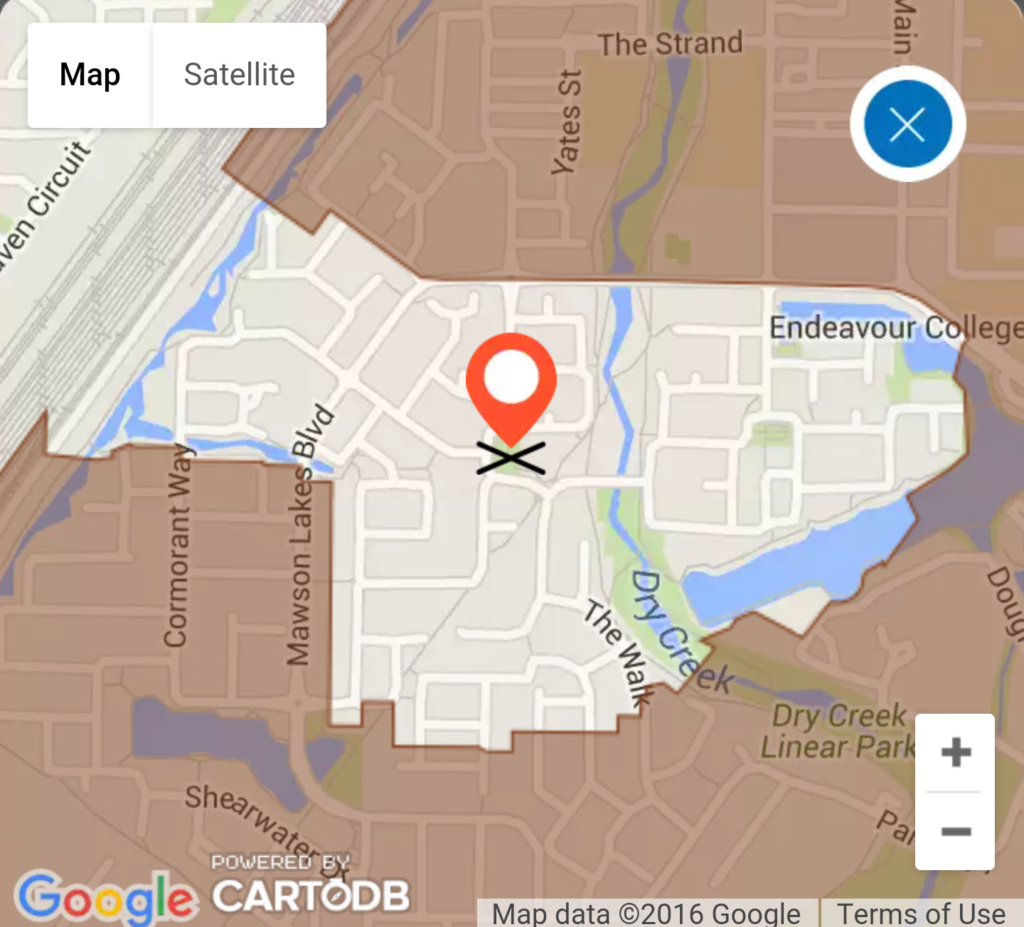
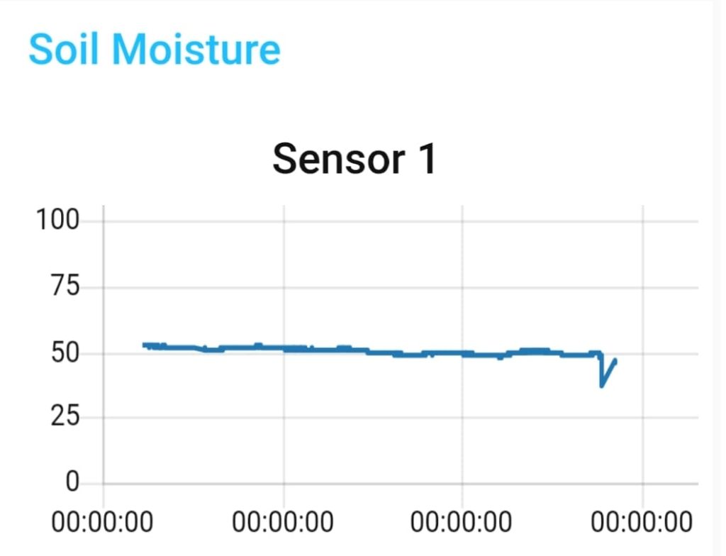
Moisture Sensor

A soil moisture sensor which sends measurements via LoRaWAN to a monitoring application created NodeRed

The data is displayed in a web browser as the following.

Next Post: IoT Workshop (Part 2)

Building a Junk Rover (Part 2)

Introduction

The Junkbote Rover

In the last article, we posted about how the Junkbot rover was built and what went into its initial construction. Since that post was written, the robot has been completed and it is now does everything it was designed to do and a little bit more.

This article will describe what has been added and changed. It then also discusses what additional things could be added or changed in the future, or included in any new robot projects. (Watch this space!)

The Junkbot appeared at the recent Science Alive 2019, at the Port Adelaide Enfield diplay, and while there, was driven around remotely, making friends with the visitors.

Completing the Build

There have been some minor changes and additionss to the robot as seen in the picture above. Cosmetically, the green button in the middle of his ‘head’ has been replaced with a red numerical display that shows the battery voltage. The black speakers (USB) below this have been replace with a larger box containing USB powered/amplified speakers that take their audio from a line-in (line-out from the Raspberry Pi computer) which are louder and are more reliable. The original USB based audio speakers would periodically just stop working.

On the side of the top grey box, a pair of sero motors have been added, one on each side. The customer will be able to add what every they want to these. These were wired to the Raspberry Pi PWN board, and can be controlled to go up and down independantly.

Driving the Robot

As mentioned in the previous article, the computer controlling the robot is a Raspberry Pi 3, running with a custom Python program which uses keybaord input to then drive the various motors and servos on the robot. The operating system bering used is Raspbian, which has a graphical desktop, similar to MS Windows or Apple iOS, but instead of displaying oit on a screen, can be shown on another computer on the network, via a program called VNC. This easily allows someone sitting at a computer screen, possibly at a long remote distance, to see what the rovers computer sees, and control it in exactly the same way as if they were sitting next to it (as if it had a screen, keyboard and mouse attached).

When running the driving software, pressing keys on the keyboard (‘w’,’a’,’s’ and ‘d’) will make the robot drive forward, left, backwards, and right. Other keys will make it move its servos up and down, as well as completely stop.

Webcam software displays the camera image, so the driver can see where they are going.

In addition, by using some standard video conferencing software (Google) , the robots speakers and microphone can be used to hold conversations with people near the rover. Voice changing software on the call add additonal interest, giving the robot even more personality.

Improvements, Upgrades and Future Plans

The rover uses the Raspberry Pi 3 computer. An immediate improvement to performance, if required, is to upgrade this to a Raspberry Pi 4, with larger memory. The board can be resonably easily swapped out, and running the new board from the existing SDcard.

The Raspbian operating system, which is based on Debian, made the task of developing the driving software, and integrating it with other standard software packages (audio, video, remote desktop etc) very easy to do. Little, if any, changes neede dto be made to get the various software packages to work together. It almost felt like cheating. If there is any other requirement for the rover (eg. adding USB Scanner) then adding this aught to be straight forward, particularly it already exists on a general purpose linux desktop system. Raspian has also been configured to work on the small Raspberry Pi, which avoids a lot of possible finiky problems with system settings that may not be suitable on a resource constrained system.

Much of the other robot software systems out there are specifically written with particular robot hardware platforms in mind, and run on predefined operating systems. An example of a Open Source option is ROS (Robot Operating System and ROS2), but these only run on particular versions of Ubuntu. It would be interesting to use ROS2, as it allows greater flexibility in how the robot can be operated, including tracking and autonomous driving modes, as well as a bunch of other robot options. The learning curve is also quite steep.

Os menioned, the driving softwareis keyboard based. It could be replaced with a graphical tool, maybe also written in Python (Qt4Py). The keyboard events could still be captured and used, but the display could be use to provide more information and create an easier way to operate the rover, An example of this migh tbe a more intuative display of the of motor tuning parameters used to drive of the motors. Getting the rover to drive straight was always little bit tricky.

Along the lines of hardware improvements and additional sensors, shaft rotation sensors could be added to the wheels to get better motion/position sensing, or accellerometer and gyro sensors. It is possible to add an Xbox Kinect sensor bar as a distance sensing camera, which would be useful if driving in an area where people might be moving.

Building a Junk Rover

Another project for 2019! I am helping build robot rover with a “junk” theme (eg.make from e-waste) for use in school education program about recycling and reuse of electronic waste.

This is being done as part of my involvement as a volunteer with Port Adelaide Enfield Libraries and their STEM Program.

Robert has built the hardware which consists of a chassis made of old computer boards. The eyes are recycled IP security cameras which no longer work. The video is coming from a webcam, and the mouth is the usual set of stereo speakers sold for use with the Raspberry Pi computer. To control the motors and other moving parts, the Junkbot uses a small Raspberry Pi computer and a 16 Channel PWM PiHat from Core Electronics.

All of this work has been done with the aim of releasing everything under Free and Open licenses (both hardware designs and software). It would be great if the project reached a point where we not only made something useful for the STEM program but that others could use as a base for their own projects. (If any of this is useful to you, please let me know.)

All of the code from this project is available at Github.

The robot is running ‘Raspbian’ on the Raspberry Pi with the Python Libraries from Core Electronics to enable the wheel motors ans servos to be crontrolled via Pulse Width Modulation (PWM) and the attached PWM board.

For better or worse it was decided to create a keyboard control interface to drive the robot. The desktop screen of the Raspberry Pi is exported over Wifi and the internet via VNC, which can be accessed via VNCviewer. Using keyboard controls we can drive the robot motors, which also allowed us to then tune it’s operation.

As an initial observation, smooth driving operation of the robot might sound like a good idea but it appears as though with remote camera access, control is better if the robot makes small moves, allowing the video display to catch up.

Tuning, modifications and upgrades continue.

More about the construction

From Robert Hart on the electronics…

Inside the head of the Junkbot

The robot will run on a S3 Lipo (on the left in the picture above). Its nominal voltage of 11.1V (3.70V*3 cells) and a fully charged 3S pack is 12.60V and a fully discharged 3S pack is 9.00V. I have incorporated two 5V buck (voltage) convertors: 5A for the Raspberry Pi and 3A for the Servo Hat. The two motors are driven using two Electronic Speed Controllers (ESC)

Waterproof Electronic Speed Controller

The ESCs have had the fans are removed and the on/off switchs have been removed and shorted. The servo lead has also had its postive wire open circuited so not to feed its 5V rail back into the Servo hat.

The Rasperry Pi and Servo Hat can be seen to the right of the box. The ESC’s are above that, with the two voltage converters at the bottom.

Adding a Dev case out of Lego

While the kids had the Lego out, I thought that I would pinch some pieces and build a case for my LoRaWAN node. Nothing fancy, random colours but enought to protect the boards from random knocks and bumps.

Blinking LEDs, improved with Lego

Technical Specifications

  • Pieces: 55
  • Colour: Various
  • Dimensions: 9 studs x 12 studs x 5.2 layers

LoRaWAN Node (Update)

LoRa Node consisting of an Arduino Uno (bottom), Duinotech LoRa Radio shield (middle) and Freetronics prototyping board (top)

The following is a quick update on the construction of LoRaWAN node., which was perviously described here.

After the previous work and the messing around with the uneven Arduino pins, I ordered some Freetronics prototyping boards and continued with those.

With the first prototype, I had attached LEDs to the first two digital pins (D0,D1) which are also used by the USB Serial connection. These made them kind of useless for monitoring any status, but also interfeared with the Arduino sketch programming. Before a new program could be successfully loaded in this configuration, the board first needed to be removed. This got annoying very quickly, particularly when I enjoy having a fast development process.

In the next design I removed these LED’s and connected them up to the supposibly free and available digital pins (D11,D12 and D13). It appears as though the LoRa radio board also uses at least one of these pins out of the box, with configuration jumpers that use the others. If the configuration jumpers are changed, the software would also need to be changed. The board works as expected out of the box with the available Arduino libraries, so it would be a pity to mess this up. Also, the documentation on the boards jumpers, and their orientation isn’t the clearest, so it would be best just to leave this well alone.

The remnants of this work can be seen on the bottom three resistors seen in the picture above. These resistors were connected with hookup wire underneath to pin D11, D12 and D13.

The Arduinio analog input pins, which were still unuised, can be switch to be used as digital outputs. The three LEDs that were connected earlier to the digital pins, were now connected to Analog pins A0, A1 and A2, with addional LEDs (with resistors, more about that sortly) to A3, A4, and A5. They are connected by more hookup wire underneath the prototype board.

Spot the difference.

A sketch was written to test the connected LED’s and was uploaded, without having to remove the prototype board first. This showed that everything was working as expected, except for one thing. The three new LEDs where significantly dimmer than the first ones.

The three new resistors I had grabbed quickly from my resistor box were 1K (Brown-Black-Black-Brown/Brown), rather than 100 Ohm (Brown-Black-Black-Black/Brown). This ment that the current through the LEDs was less, and hence their brightness was less as well. This has not been fixed in this prototype and probably wont be, although I could solder another suitably size resistor in parallel to the 1K ones to made the combined resistance close to the desired 100 Ohm amount.

The uploaded sketch was still contained the ability to set a couple of LEDs based on a byte of data received from the LoRaWAN radio. This was shown to work from The Things Network web, with the next step being able to drive this from custom software. Data from the LoRaWAN node is accesses via the MQTT protocol, and data can be uplinked to the node using the same method.

I have created several utility scripts to test all of this, which can be found on GitHub at: https://github.com/PaulSchulz/ttn-utils

LoRaWAN Node and Gateway

LoRaWAN Node and Gateway

With assistance of the STEM Education resources from the Port Adelaide Enfield Libraries, I have been investigating LoRaWAN devices, how to build them and how they can be used.

There is more investigation to be done, but the node shown in the picture above is able to do the following:

  • Connect and Authenticate to a LoRaWAN network (The Things Network) via Over The Air Authentication (OTAA); and
  • Send data (Uplink) and Receive data (Downlink) via the LoRaWAN Gateway(s). (Downlink data is queued, and is received in a window after Uplink data has been received by the network. This reduces power usage in the node.)

The Node used was the Gragino Arduino Shield (or clone from duinotech)

The Gateway is the uGateway LoRaWAN from Core Electronics. Having a local gateway is not necessary if there is another one in the neighbourhood, within range of your node. There are currently no nodes in my area so an internal gateway was required for development and testing. The other option was to take the Node for a drive in the car after a development session, but this made debugging very tiresom, very quickly.

There are a couple of other useful tools worth mentioning.

TTN Mapper is an Android application that will monitor your device on your smart phone, via The Things Network. It then used your phones GPS to log the position of your device. The result is that you can map the coverage of nearby gateways by using your LoRaWAN node and phone in a similar way to how Wireless Access points used to be mapped (WarDriving). This is useful for knowing where your nodes have TTN access, and where additional gateways might be required.

NBN via HFC delivered to Parkview Village

NBN arrives in Mawson Lakes

It’s finally arrived. Twenty years after being promised a community with a broadband infrustructure it has finally been delivered to the Mawson Lakes Parkview Village via NBN’s NFC infrustructure.

It would be interesting someday to get the details of what exactly happened, but the end result was that the early parts of Mawson Lakes had coax cable in the street, which the later parts didn’t. In addition to this, much of the earlier sections were also put on ‘pair-gain’ for their home phone which ment that the new ADSL technology for broadband over their phone line were also not available. Many homes opted for fixed wireless connections, which can be verified by the large number of wireless dishes on the roofs across the neighbourhood.

When we originally bought our property in 1998, it was with the promise by the developer that Mawson Lakes residents would have access to broadband when they moved into their homes. This was before the 2000 Sydney Olympics and the Optus vs Telstra cable wars, which saw large amounts of cable rapidly rolled out across Australia through this period, through to mid-1999.

The Mawson Lakes Foxtel Cable, now HFC Network Area

The developer Delfin, now Lendlease, had made an arrangement with Telstra to do the rollout in Mawson Lakes. When Optus decided to stop, Telstra also stopped it’s rollout nationwide, including Mawson Lakes, even though a separate cotract was in place. My understanding was that the contract commitment by Telstra Delfin was eventually settled out of court for an undisclosed sum..

While having waited so long for the internet service that had originally been promised, I there was happy enough to be able to pre-order the service when this option became available. This ment that finally there was some progress. The order progressed and was eventually booked in for the week before Christmas.

The installation almost happened without any drama whatsoever. A combination of the way the NBN has been designed (as a wholesale business) and the ISP, ment that not only did the process become incredibly frustraiting, but this frustration could easily have been avoided in several different ways, including not making a simple mistake in the first place.

Mistakes happen, this is a reality of life.

In this case, the serial number, or MAC address of the ISP supplied router had been entered incorrctly, presumably by the ISP. I have no way of knowing if this was indeed the case or not, as the NBN technical support person wasn’t allowed to directly talk to me (as I overheard on the second call out), but the problem was solved between the NBN and my ISP in the background while I waited. This is what happens when you pay peanuts for data entry. On the first visit the NBN installation was done and everything from their point of view was working as expected, so the technision left. The router was ment to self-configure, which it didn’t, so several calls were made to the ISP and a second NBN callout was eventually made four days later.

In the meantime, on the day that the NDN as provisioned, my perfectly functional ADSL service was disabled and the login removed. After several calls, I was able to get a temporary login setup for this service so the family could atleast have internet access over Christmas. ATt this point the problem with the NBN service had yet to be identified. A further call to the ISP was required as they then attempted to bill me for the temporary.

In sort, not only did I fail to get a working ISP/NBN service, but the existing functioning ADSL service was cut off, with no expectation given on when any of the issues would be resolved.

Amongst all of this rant, there are a couple of highlights. I can report that there are still some knowledgable tech support people around who know the systems well enough to fix an issue without following a script. They are rare though. I hope they are being paid enough.

Code for Cosmic Array Sensor Project

A recent project has been pulling together some code for a Raspberry Pi Zero, which is going to be part of the system in the a Cosmic Ray Sensor. Details about the The Cosmic Array project, which is part of the Splash Adelaide Winter Festival are available from the Hackaday Website.

The Raspberry Pi takes events from the sensor and plays chimes depending on the direction that the detected muons appear to come from (via a coincidence circuit).

paul

May 31, 2016

detourJust got off the phone from Salisbury Council about the road works an detours that are going on around the place. I got caught out yesterday, doing a last minute ‘Oh we all slept in!” dash, and ended up going a lot further than we needed to.

The details that I have:

  • Mon, 30th May –  Fri, 10th June: Mawson Lakes Boulevard – Closed from Parkway to Mary Street (Montague Road end). North detour back via Parkway in Technology Park.
  • Mon, 6th June – Thu, 16th June: Mawson Lakes Boulevard – Works at the Peninsula Drive and Parkway Drive Roundabouts.

Hopefully these two road closures won’t overlap by too much.


Just had a letter in the mailbox with more details, and I have rung Adrian, the Surfacing Coordinator to confirm access during these times. The plan at the moment(1 June) subject to weather:

  • Monday – Work starts on Peninsula Roundabout, Work starts on Parkview Dr. Roundabout.
  • Tuesday – Work starts on Parkview Dr.
  • Wednesday – New Asphalt put down on Parkview Dr.

Local access will not be completely cut off during this time, works start at 7am,  but there may be some delays getting in and out of adjoining roads. Access will be available after 5pm each day. Direction will need to be taken by road management services.

I will continue to update this post if I find out any more details

Adelaide Internet of Things (IoT) Hackathon

Yesterday (Sat, 23 April 2016) saw the first Adelaide IoT Hackathon held at the Smart City Studio in the City of Adelaide.

This author is very please to announce that we were successful and won the event with our project: City wide water leakage monitoring. We were us against the 10 Cent – Internet of trash and an Interactive Electronic Notice Board. The decision was very tough according to the judges.

The prizes include access to IBM’s IoT and Cloud platforms. We will be updating the Hackaday page above with more details as we progress with the project.