Introduction

In the last article, we posted about how the Junkbot rover was built and what went into its initial construction. Since that post was written, the robot has been completed and it is now does everything it was designed to do and a little bit more.
This article will describe what has been added and changed. It then also discusses what additional things could be added or changed in the future, or included in any new robot projects. (Watch this space!)
The Junkbot appeared at the recent Science Alive 2019, at the Port Adelaide Enfield diplay, and while there, was driven around remotely, making friends with the visitors.
Completing the Build
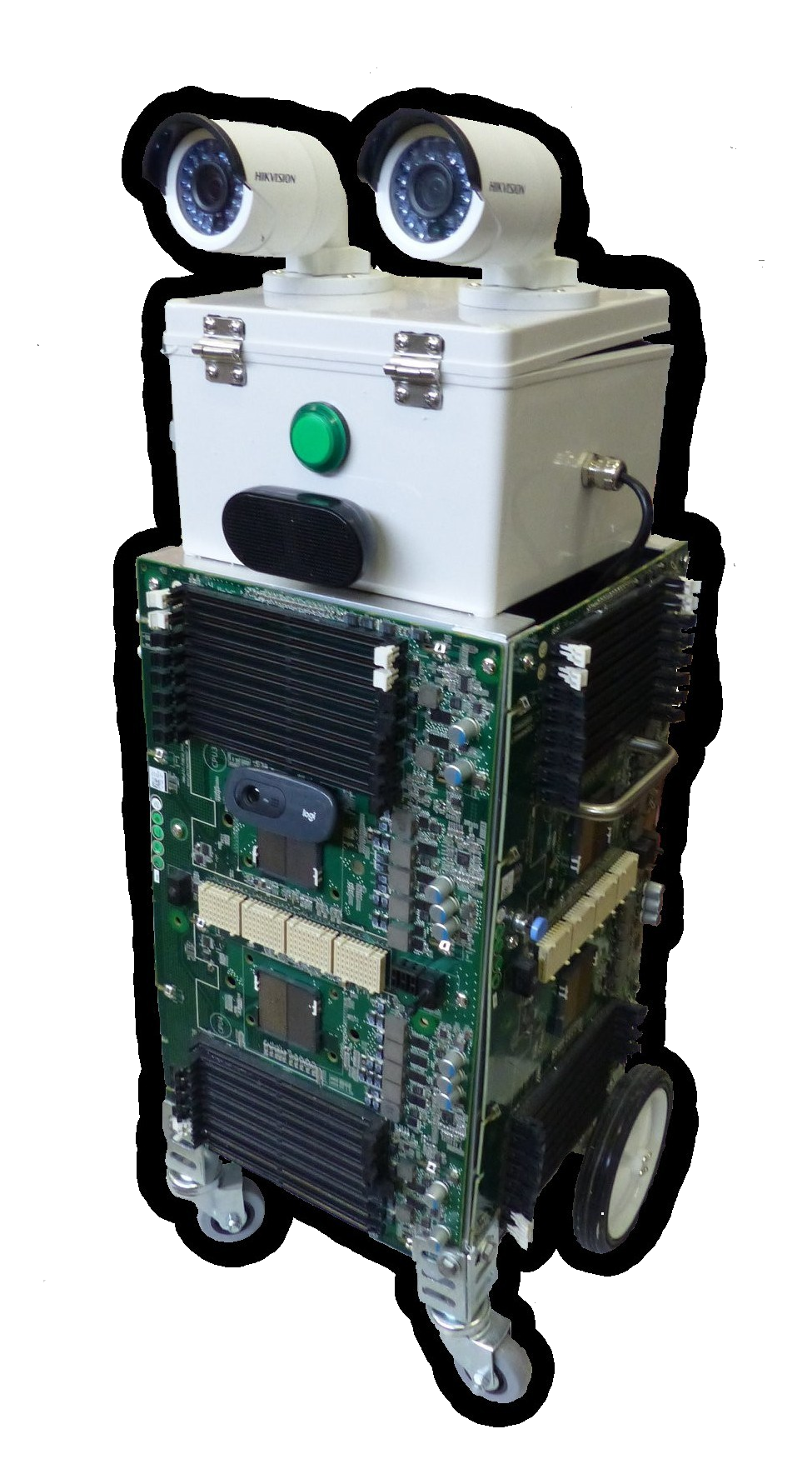
There have been some minor changes and additionss to the robot as seen in the picture above. Cosmetically, the green button in the middle of his ‘head’ has been replaced with a red numerical display that shows the battery voltage. The black speakers (USB) below this have been replace with a larger box containing USB powered/amplified speakers that take their audio from a line-in (line-out from the Raspberry Pi computer) which are louder and are more reliable. The original USB based audio speakers would periodically just stop working.
On the side of the top grey box, a pair of sero motors have been added, one on each side. The customer will be able to add what every they want to these. These were wired to the Raspberry Pi PWN board, and can be controlled to go up and down independantly.
Driving the Robot
As mentioned in the previous article, the computer controlling the robot is a Raspberry Pi 3, running with a custom Python program which uses keybaord input to then drive the various motors and servos on the robot. The operating system bering used is Raspbian, which has a graphical desktop, similar to MS Windows or Apple iOS, but instead of displaying oit on a screen, can be shown on another computer on the network, via a program called VNC. This easily allows someone sitting at a computer screen, possibly at a long remote distance, to see what the rovers computer sees, and control it in exactly the same way as if they were sitting next to it (as if it had a screen, keyboard and mouse attached).
When running the driving software, pressing keys on the keyboard (‘w’,’a’,’s’ and ‘d’) will make the robot drive forward, left, backwards, and right. Other keys will make it move its servos up and down, as well as completely stop.
Webcam software displays the camera image, so the driver can see where they are going.
In addition, by using some standard video conferencing software (Google) , the robots speakers and microphone can be used to hold conversations with people near the rover. Voice changing software on the call add additonal interest, giving the robot even more personality.
Improvements, Upgrades and Future Plans
The rover uses the Raspberry Pi 3 computer. An immediate improvement to performance, if required, is to upgrade this to a Raspberry Pi 4, with larger memory. The board can be resonably easily swapped out, and running the new board from the existing SDcard.
The Raspbian operating system, which is based on Debian, made the task of developing the driving software, and integrating it with other standard software packages (audio, video, remote desktop etc) very easy to do. Little, if any, changes neede dto be made to get the various software packages to work together. It almost felt like cheating. If there is any other requirement for the rover (eg. adding USB Scanner) then adding this aught to be straight forward, particularly it already exists on a general purpose linux desktop system. Raspian has also been configured to work on the small Raspberry Pi, which avoids a lot of possible finiky problems with system settings that may not be suitable on a resource constrained system.
Much of the other robot software systems out there are specifically written with particular robot hardware platforms in mind, and run on predefined operating systems. An example of a Open Source option is ROS (Robot Operating System and ROS2), but these only run on particular versions of Ubuntu. It would be interesting to use ROS2, as it allows greater flexibility in how the robot can be operated, including tracking and autonomous driving modes, as well as a bunch of other robot options. The learning curve is also quite steep.
Os menioned, the driving softwareis keyboard based. It could be replaced with a graphical tool, maybe also written in Python (Qt4Py). The keyboard events could still be captured and used, but the display could be use to provide more information and create an easier way to operate the rover, An example of this migh tbe a more intuative display of the of motor tuning parameters used to drive of the motors. Getting the rover to drive straight was always little bit tricky.
Along the lines of hardware improvements and additional sensors, shaft rotation sensors could be added to the wheels to get better motion/position sensing, or accellerometer and gyro sensors. It is possible to add an Xbox Kinect sensor bar as a distance sensing camera, which would be useful if driving in an area where people might be moving.