Tag Archives: pedal-power

My Anderson Powerpole Connector crisis is over..

After forking out $5 for a single set of Anderson Powerpole Connectors from Jaycar I thought that I would bite the bullet and purchase enough from the US supplier so I wouldn’t have to worry about this any more.

The above photo shows the connectors in groups of ten, so I could easily count them. I purchased 100 sets from Powerwerx at $0.87 each including shipping, just in time for the Amateur Radio John Moyle Field day.

Powering the OLPC XO-1

Another device that I thought would be worth trying out with the generator is the laptop from the One Person Per Laptop project, the XO-1.

I have been fortunate and have acquired two of these XO-1’s (sparky and sparks). Both of them were pre-release versions and have been superseded in various ways, but they still attach attention when brought out on display. Kid’s just love them.

Both XO’s were able to be run via the inverter from their charge packs. (One of them has an issue with it’s battery taking a charge, which is why it is off in the photo.)

When I get some more Anderson connectors I’ll look at how they go when connected directly to the 12v-14v supply.

First Power Generation Application

I didn’t have any luck finding my 240V inverter, but I was able to borrow one from a friend (in exchange for fitting it with an Anderson Powerpole connector.)

So, you have a peddle powered generator.. what’s the first application or device that can be tested with his new power source? Being Australian and and an Amateur Radio operator, the first device had to be a radio. (For overseas readers, Australia has a proud history of peddle powered radios, which together with the Flying Doctor service, brought emergency healthcare to the centre of Australia.)

The second application was therefor a peddle powered television.

The small television did not have a rating listed on it anywhere, but after peddling for 30 minues or so, while catching up on the evening news, I would say that it is about 25 or 30W. It is uncertain what the efficiency of the inverter is at this stage.

I see this setup quickly becoming a core part of my exercise program.

Anderson Powerpole Connectors

With my increasing number of 12V appliances, thoughts quickly turned to what would be an appropriate standard power connector. In the past, these appliances have had a huge range of different sized cylindrical or barrel plugs with different polarities, typically powered by a 240V plug pack.

One DC power connector which has gained some prominence is the ‘Powerpole’ or ‘Anderson’ connectors. These connectors have been chosen as the standard DC power connector for Amateur Radio operations, particularly where emergency and disaster relief operations are in mind. (eg. with WICEN)
These connectors have a couple of unique features. The most obvious is their shape.The ‘plug’ and ‘socket’ ends are identical (and symmetric) and can be used as either end of a connection. The blade contacts themselves are self cleaning, in that the motion of connection and disconnection allows the terminals to scrape any foreign material from the electrical connection area.
For those mathematically astute people, the connectors are symmetric under a rotation group. (Look out for further discussion of this in another blog post.)
The connectors come in several different ratings, but for the most common sizes for which I’m interested (15amp, 30amp and 45amp), they share the same plug enclosure, but take different sizes/gauge of wire.

There was some research required to relate the US wire specification (maximum current and gauge) with the Australian ratings (maximum current and cable cross section.) Bunnings sells cable for outdoor lighting, which had a cross section of 3.3mm^2, which corresponds to 12 gauge wire, the size that is rated for 30amps. This cable is twin core and all black, not the pretty red and black ‘zip cord’ that is available from the Anderson Connector distributor, but I can’t see any reason why it wouldn’t work.
For more information on Anderson Connections see the Powerwerx website (a distributor).

Pedal Power Update

A very useful site is the one for Bosch, which produces the after market replacement and spare engine alternators. The PDF downloads from this page have all the technical specifications of the alternator for each vehicle engine type. (Ed Update: Google ‘Bosch Alternator Wiring’ should find the details that you are after.)

The budget

Someone has asked about what the budget was… I have spent maybe $250 up to this point, but now knowing what I need it would be a little less. Some things could be purchased on e-Bay etc.

  • Bicycle – Already had this, and can continue to be used as per normal.
  • Bicycle trainer $115 on ebay (mine was new) (eg. http://shop.ebay.com.au/?_nkw=bicycle+trainer) Remove and throw away resistance roller.
  • Alternator $55. From City Dismantlers, Gepps Cross (Toyota Section) Connecting plug – free – worth asking for it when you get the alternator, as mine was stripped from the wiring of a wreck.
  • Old wooden shelving $??. It’s what I had lying around.
  • Assorted Hardware: screws, bolts, toggle maybe $60. I used stainless steel toggle for tensioning, and Stainless U-bolts to clamp the trainer to the board. (Not the cheapest solution, but reusable parts.)
  • Aluminum L section (cut and drilled to suit) $6 Purchased from Bunnings in 1.6m lendth.
  • 12V Battery (required) $28 from Jaycar 12V 6AH Sealed Lead Acid. No reason for this specification other than this is what I had around.
  • Switches with ‘missle cover’ $12. Always wanted on of these I want to install add a couple more.. a second one to switch the ‘load’ on… alternator has some trouble starting to generate if another load is pulling from the battery, and on to isolate the battery.
  • Spade and Blade Crimp connectors $2.75 (per pack of 8) Various sizes. Still need to find proper size for battery terminal connection to alternator.
  • Cables $?? Scavenged from various bits and pieces. Plan to use regular extension cable (from Bunnings) to extend ‘Ignition’ and ‘Load’ switch so that they are accessible from the handlebars while on the bike. (I might have to rethink this as these are rated for 10A AC, and some of the applications that I am looking at use 30A rated wire.
  • Anderson Connectors $5 pair from Jaycar. I would like to replace the spade and banana plug connectors that are currently being used, with Anderson 30A connectors where ever possible. (This will be the subject of another blog post with links.)

I have also bought a couple of boxes from Jaycar to mount these swithes, as well as two LED’s (and resistor) that replaces the usual ‘charge lamp’.

Other considerations/thoughts/things to try..

I have tried making a radio call from the bike, powering my Handheld radio. There was sufficient noise on the supply to be heard on the output, while both receiving and (as reported) transmitting. Some work needs to be done to remove this (Large Capacitor + something else.. got some Amateur Radio friends on the case).

I have a small 240V inverter around somewhere. If I find it, I’ll see if it is possible to run a small TV directly while peddling.

A summary, of sorts.

Nothing in this project has really been engineered so I would like at some stage to take a bunch of measurements and do some calculations on the systems efficency etc.

For example, I would love to get a ‘current clamp’ and get some measurements of the running generator under different loads.

The alternator has a build in voltage regulator, which works by modifying the current in the rotor windings. This means that the choice of peddling rate doesn’t particularly matter (voltage remains the same) and the gearing is sufficient to spin up the alternator to fairly high RPM’s if required (calculation required).

Thanks everyone for your interest.


Update Fri, 24 July 2015: Article transfered to new MawsonLakes.Org website. Minor edits and updates made.

Building a Pedal Powered Electric Generator

Greetings.. over the last couple of months, thoughts and materials have been gathering in order to build a pedal powered electric power supply, which could be used, amongst other things to recharge batteries and to power an amateur radio transceiver.

I am pleased to announce that the first stage of construction, getting an vehicle alternator to reliable produce power, has been achieved.

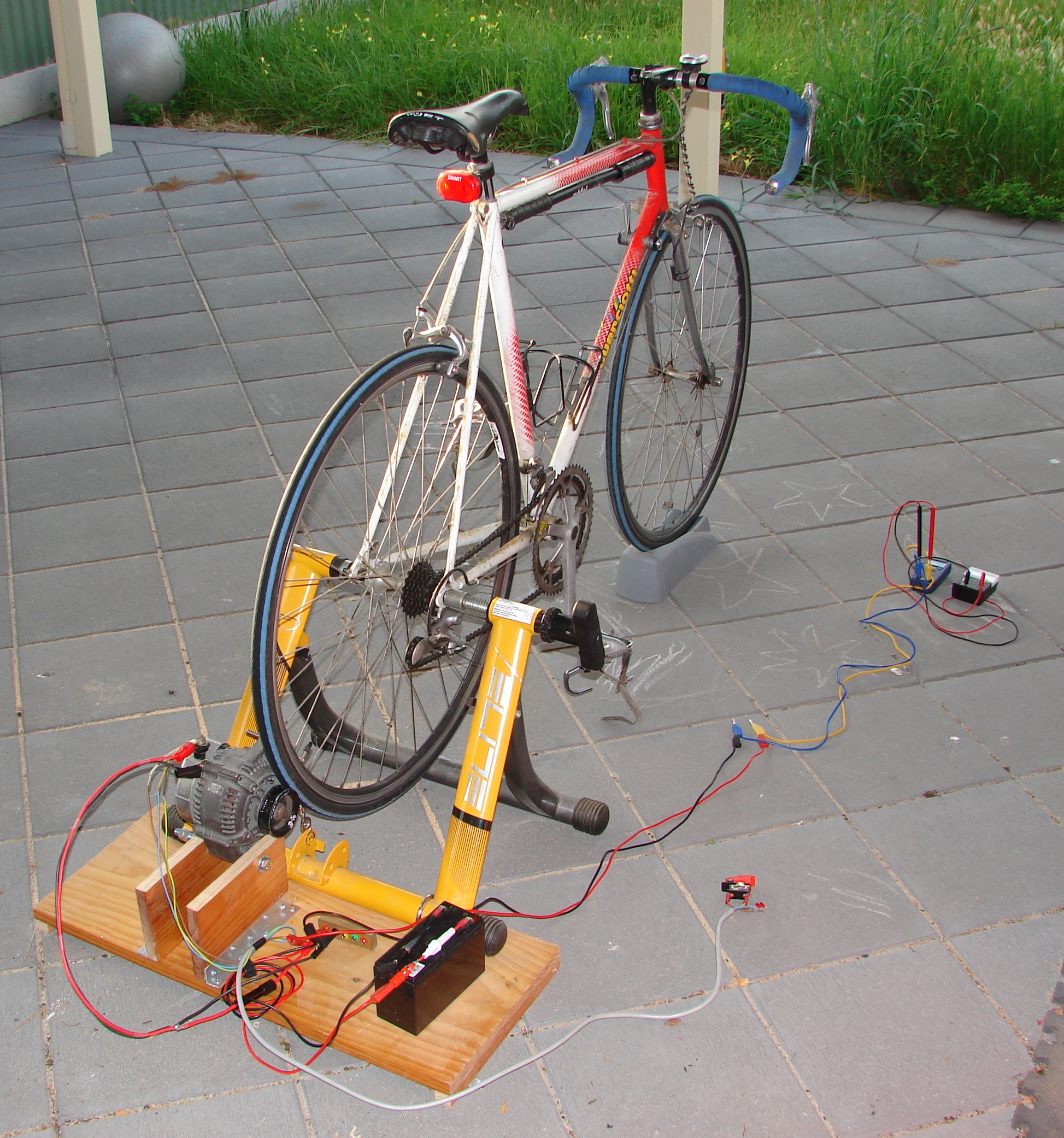
Pedal Powered Alternator – Stage 1

Stage 1 involved getting the alternator mounted properly and generating a stable output voltage.. which it did at 14.7V. This lets the alternator recharge the battery.

What has been constructed?

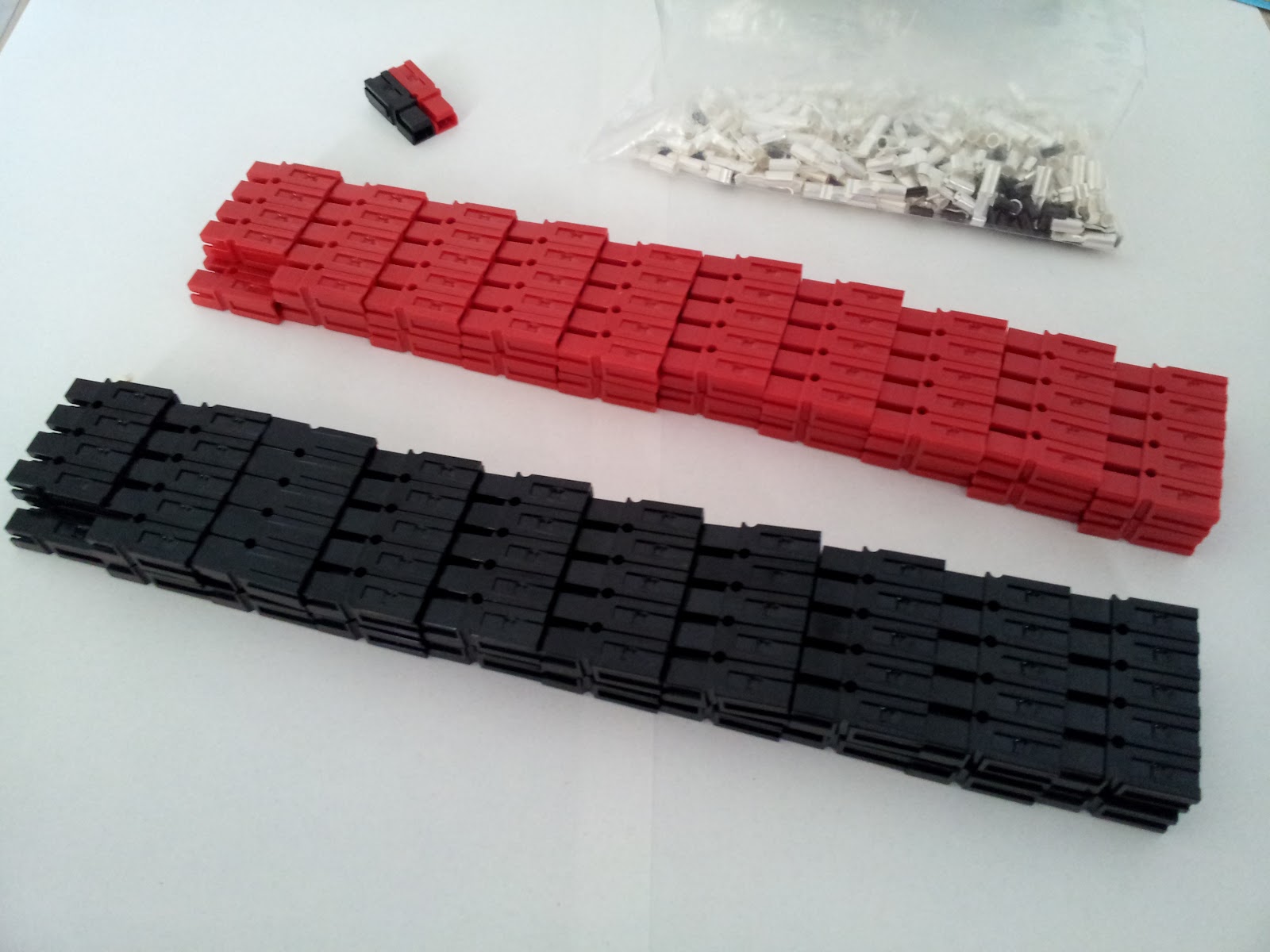
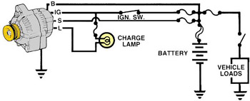
Step 1 – The alternator and wiring harness.

An alternator from a local used car parts dealer was purchased. I picked up a Toyota alternator for $55 at Gepps Cross wreckers. I started to build up the wiring harness.. it wasn’t really possible to test anything properly as (apparently) the alternator only starts to kick in at around 800-1000 RPM. Some quick calculations indicated that that the racing bike would be able to do provide this (with a direct friction drive with the wheel) at reasonably low speed (6km/h – simulated, it’s on a trainer.) It may be necessary to even further reduce the ratio by fitting a larger wheel to the alternator. This would also help with the traction if it was something like a go-cart or small sack truck wheel.

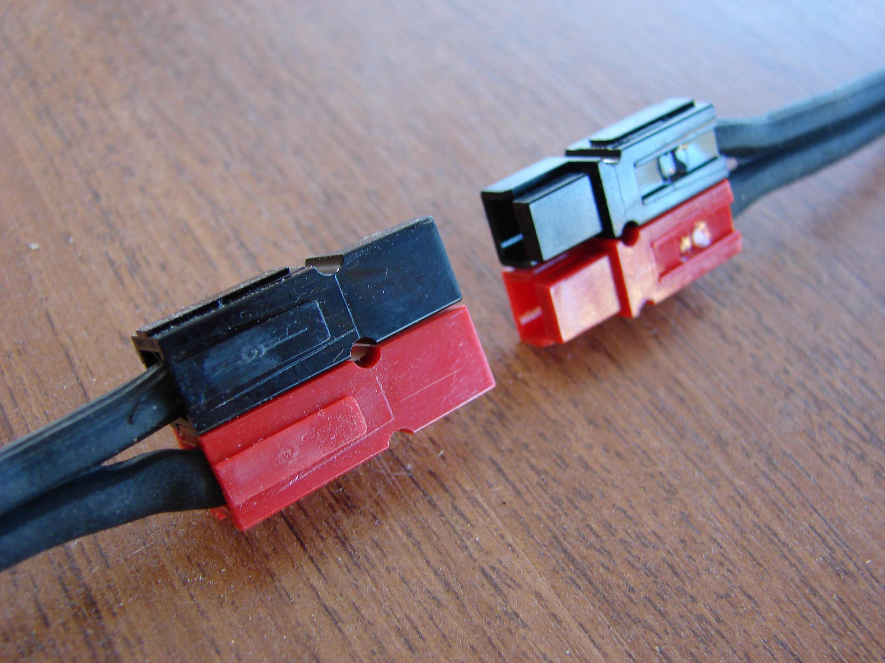
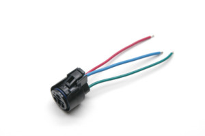
When obtaining the alternator, it is definitely worth asking for the connecting plug at the same time. Mine was stripped from a wreck at the wreckers, and supplied for no cost, which was quite handy. (I did have to go back the day after to ask about getting it though.)
Wiring_harness_500
The alternator was connected up like this… no charge lamp was used at this stage.
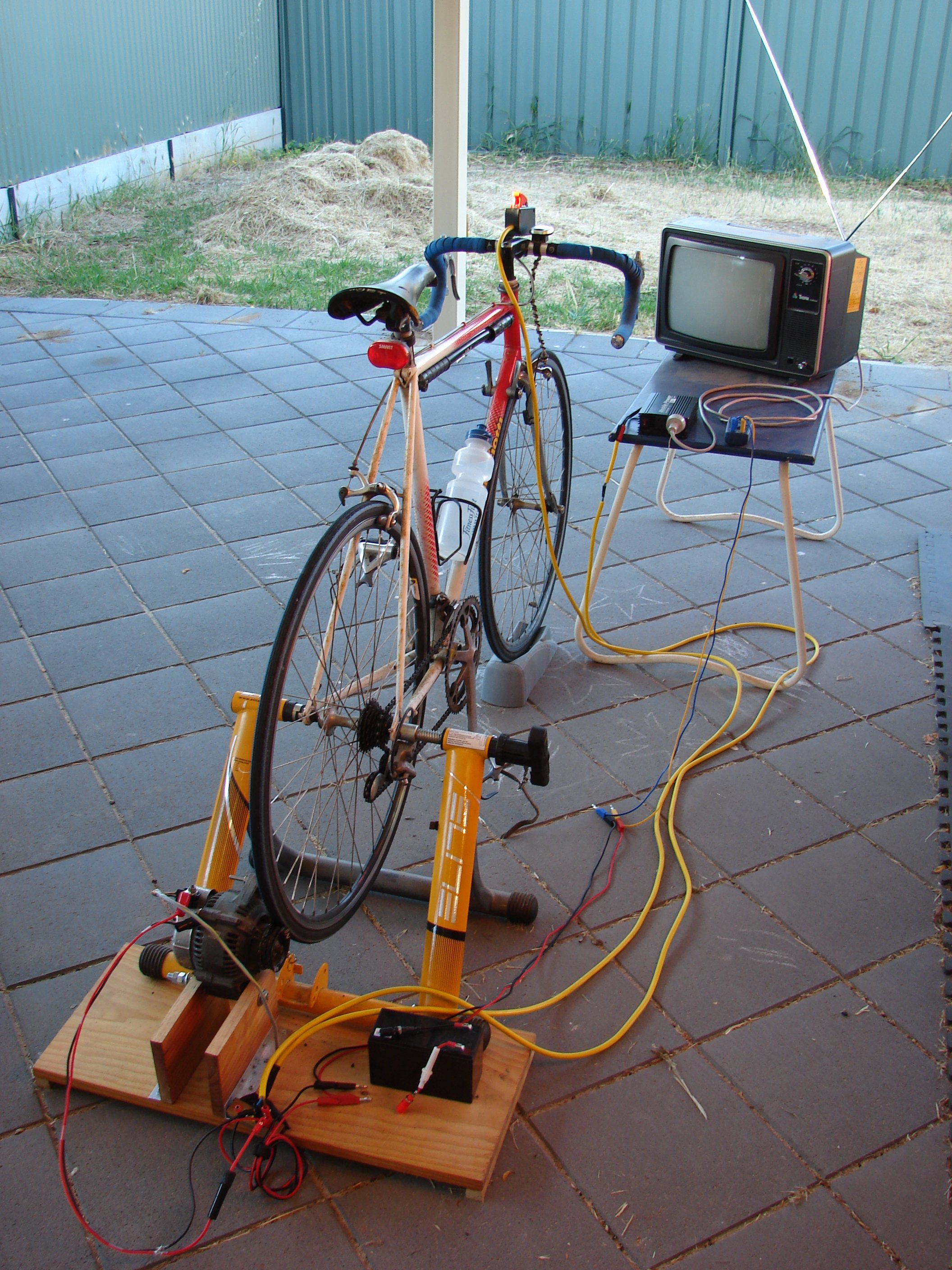
alternator-wiring

Step 2 – Mounting.

The mounting for the alternator was the biggest concern. It needed to be sturdy enough to hold the alternators weight and allow it to be held against the bikes tire and be rigid so that there weren’t issues with vibrations as the alternator and the bike wheel were spun up.

A mount made out of welded steel would have been possible, but an old pine board was also handy and fitted the bill quite well. A length was cut to go under the rear struts of the bicycle trainer, and the couple strips of wood were added for feet. The trainer was bolted down to this with a couple of 50mm stainless steel u-bolts.

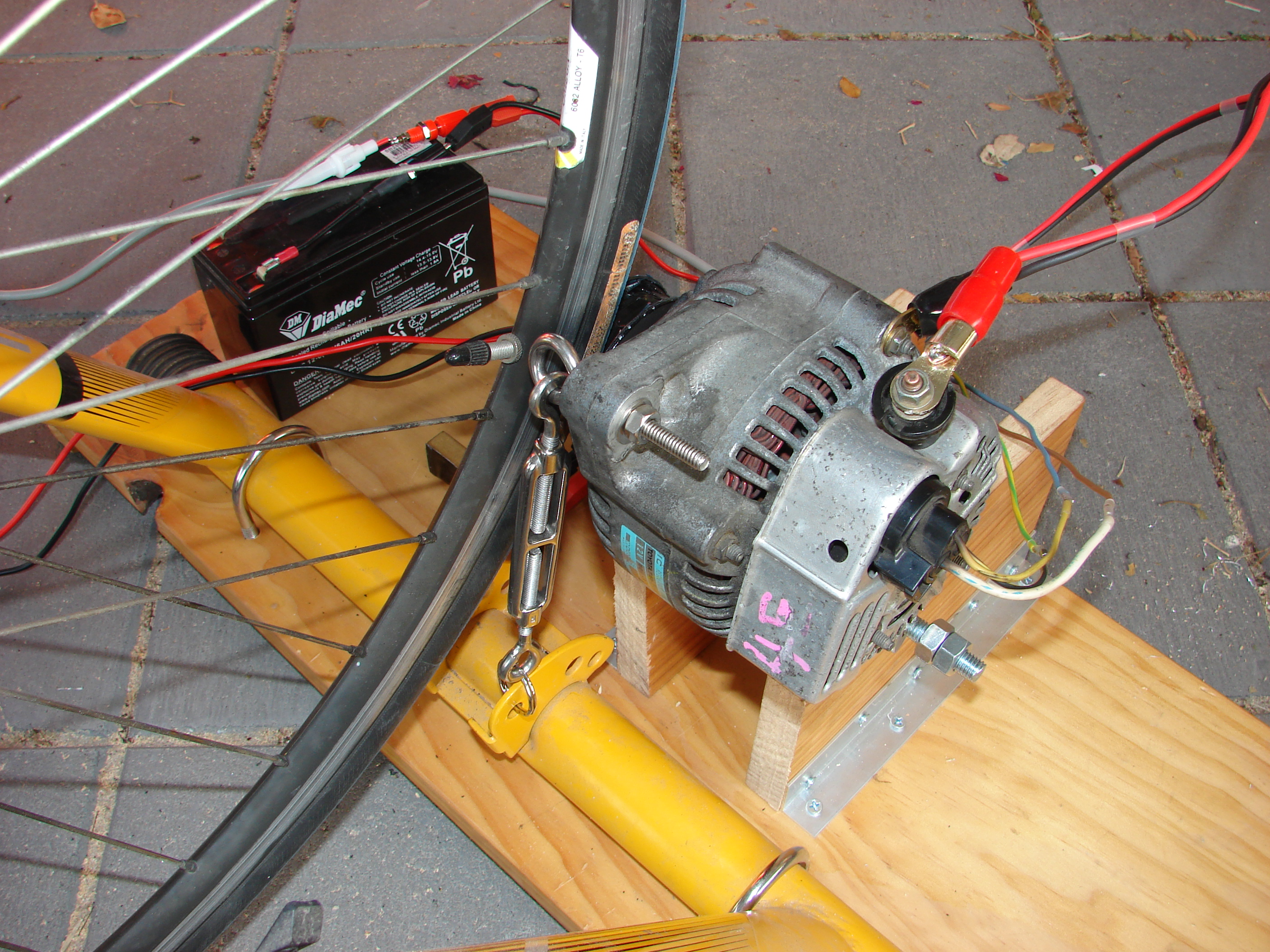
A stand for the alternator was built from couple of pieces of pine board, length ways. The alternator was mounted by drilling a hole through the boards for a bolt, which allowed the alternator to pivot against the rear wheel of the bike. These boards are held in place by two full length brackets made from aluminium L sections, cut and drilled to suit.

dsc05473
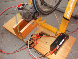
The final piece of the mounting is an eye-bolt through the other mounting hole on the alternator and a toggle connected to the base of the bicycle trainer stand (where a suitable hole had already been placed), which holds the alternator against the tire.

dsc05474

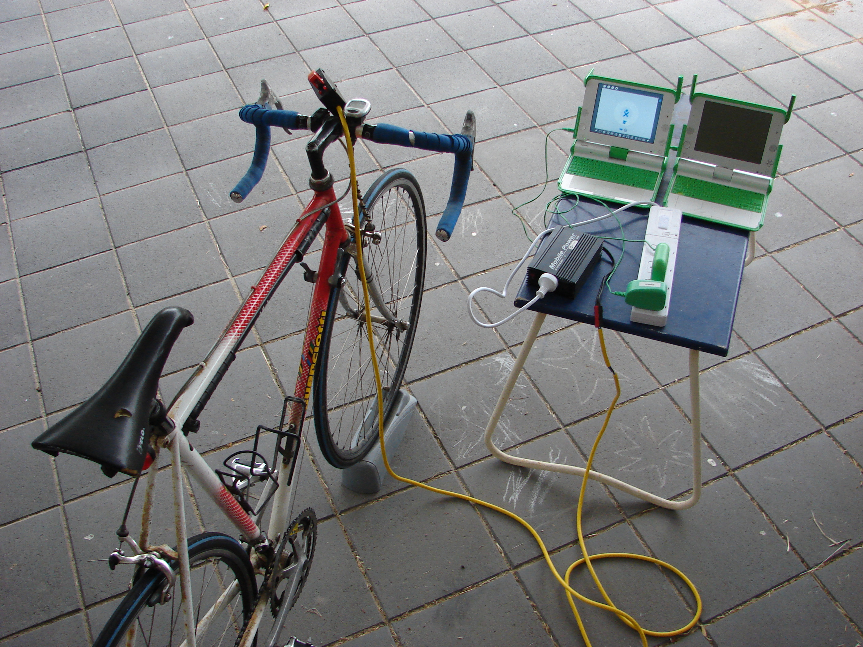
Step 3 – Assembly and Testing

Everything was assembled and a couple of trial hand cranks were done to run the alternator up. Everything ran smoothly without the alternator energised to produce power.

With the ignition switch on, but with the alternator just resting against the bike tire, the surfaces would slip as the alternator started producing power. This was solved by adjusting the tension in the toggle bolt holding the alternator against the tire.
dsc05478
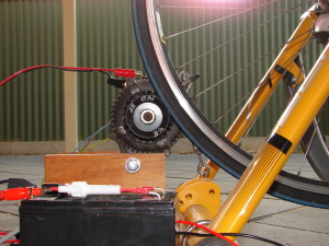
While peddling, the alternator produces 14.7-14.8V, and can be used to charge the battery that is currently attached.

What next?

The next step is to see what the system is like generating power for various loads.. and then use it to produce power for real world applications.

I plan to have it on display at the upcoming “Wireless Institute of Australia” National Field Day (aka. national publicity day)on the 23rd of October outside of the Bunnings at Parafield airport.


Update

The local “WIA National Field Day” event ended up being held in the Salisbury Town Centre (2010) and the generator was successfully demonstrated to work well recharging a battery for a Amateur radio.

This  article was originally published at “MawsonlakesOrg” on Blogspot