Four weeks to go! I sent the following message out on Sunday, 11th to the people who had RSVP’d the event that I am hosting in Adelaide for the Home Assistant Community Day. This was the inaugural event for South Australia.
It would be awesome if you could make it.
Greetings
There are four weeks to got to the Home Assistant Community Day on Saturday, 7 November, and we already have 14 people who have RSVP’d. Thank you very much, I am so looking forward seeing you all on the day
In the meantime, there are a couple of things I would likle to mention.
Next week on Sunday, 18 Oct, the “Automation, Robotics and IoT” community group will be meeting at 1pm, at the came location at the Parks Library. We will have time to talk about possible activities for the Community Day Event.
Is there anything Home Assistant related that you could bring talk about, demonstrate or present?
Would anyone here find it useful to have a brocure or invitation for the Community Day event that they could give to other interested people? (or should we try to do this all electronically? The link to the event on Luma is – https://luma.com/hb4tgbbw )
Thank you again for RSVP’ing, and we will see you all on the day, maybe sooner.
To make use of renewable energy effectively we need to have the following information.
When importing or exporting energy from the grid, where the energy is priced under a variable, time-of-use tariff, customers need to have usage data that is:
real-time (per second if possible) – so that we can see when we are using our energy;
reporting total energy imported and exported, with a power measurement for energy used or generated – so we can see how much power we are importing or exporting;
locally available via a local serial/wired port/connection to a local energy management system – so that operation is unaffected if there is any form of internet access;
the same as the billing data– so that bills can be independently verified when the data is combined with the applicable tariffs.
This is the minimum requirements.
So, where is the problem?
Energy systems being installed for NEM customers at the moment provide none of these, not completely.
The rules that govern the NEM, as specified by the AEMC, were changed in December 2025 to include rules covering “Real-time data for Consumers“.
Contrary to the points mentioned by AEMC Chair Anna Collyer in the above article, this rule change does nothing to meet the needs of retail customers. It introduces mechanisms by which the energy industry legally gets more detailed data about your energy usage, and gets to charge you for the systems that they now get to implement.
It would cost a minimal amount to modify smart meters to provide all of the above requirements, for all Australians. (None of this is new, and has been a standard in Europe for 18 years.)
Why is this important?
Australians are angry at the way that electricity prices are constantly going up. We are angry at politicians how say prices are coming down, but the energy industry in still able to charge its customers more.
Here was one way that the industry could have very easily given customers something back. Something that cost the industry very little, was genuinely useful to everyone’s’ energy future, and provided some hope that the industry is able to meet Australia’s needs.
TL;DR My Samasung S22 started rebooting. I have tried several thing to fix, but still needed to do a reset to “Factory Defaults”. Still testing.
Overnight my Samsung S22 started rebooting itself. This happened throughout the day, sometimes continuously and sometimes with enough of a delay to unlock the phone and start using it… only to find it rebooting soon after.
Internet searches suggested three things it could be.. the UI; a hardware issue; or third party software. I am also wary of the the newly discovered Linux kernel root access exploits, which together with the AI tools around today, could easily be exploited very quickly.
One thing that I did notice was that the phone appeared to also be slower in its responsiveness and then crash. On its return, even thought it had rebooted, all of the apps that were opened still appeared to be running, and it was only the UI, and not the system that had crashed and recovered.
There also didn’t appear to be any heat issues.
While attempting to stream some sport, I noticed that the phone didn’t reboot, until I dropped out to look up something on Chrome. This was fortuitous, as, on a whim, I upgraded Chrome, and the phone suddenly appeared to go back to its old self, and, so far so good.
Under full disclosure, here are some of the other things I tried: Clear up some space by deleting some videos and photos(in case lack of space was causing the problem); ensured that the phone was fully charged including wireless charging (maybe there was a USB driver issue); clear the UI cache (suggested by google).
Things I didn’t try: Put the phone in the freezer (suggested by Google); Delete apps (also suggested by Google but I hadn’t installed any to cause the problem).
This post has been added just in case someone else has the same problem with their Android phone. Hopefully the AIs will find it.
The phone has continued to reboot overnight. A full factory reset has been done.
Even though the rebooting is still occuring, it feels like a software, rather than a hardware issue.
The input will freeze, and then after a delay the UI will restart via a reboot. This is not a direct system crash, which i would expect would be more sudden and more repedative.
The next step.is to see.of there is a system update available.
While preparing a presentation for the Everything Open 2025, I have found a new word which I intend to use – meshaging.
I am defining this as “messaging, over open and uncontrolled mesh networks”. At it’s simplest, is could be used to describe the distributrion of a message via gossip amongst a group of friends, but also how messages are sent to a group on a mesh network like Meshtastic.
I thought I might also ask ChatGPT about the word, and this is what I got:
You said: Do you have a definition for the word “meshaging”? ChatGPT said: The term “meshaging” does not appear to have a standard or widely recognized definition in English, at least as of my knowledge cutoff and the latest updates. It could be a coined or niche term in a specific context, possibly blending “messaging” and “mesh” (as in mesh networks or interconnected systems).
If you encountered “meshaging” in a particular domain, such as technology, networking, or marketing, it might refer to:
Mesh Networking Messaging: Communication methods specifically designed for or used within mesh networks (networks where nodes communicate directly with one another without relying on a central hub).
Interwoven Messaging: A metaphorical concept where messages are interconnected or interdependent, like threads in a mesh.
A Typographical Error or Variant: It might be a typo for “messaging.”
Can you provide more context? That could help clarify its intended meaning.
You said: Can I claim to have invented the word? ChatGPT said: If “meshaging” isn’t already in use or widely recognized, you can certainly claim to have coined or invented it, especially if you can define its meaning and provide a context for its use. Here’s how you can solidify your claim:
Define the Word: Clearly state what “meshaging” means and the context in which it applies. For example:
“Meshaging” refers to the process of sending interconnected or distributed messages in a mesh network or system.
Or “Meshaging” describes a method of seamlessly blending messages into a cohesive network for enhanced communication.
Publish or Document Its Usage: Write an article, blog post, or social media post introducing the term and explaining its significance.
Use It Consistently: Apply the word in your projects, conversations, or writings to establish it as part of your lexicon.
Optional: Trademark or Copyright: If you plan to use “meshaging” as a brand or for commercial purposes, you can consider trademarking it to solidify your ownership of the term.
Claiming to have invented a word is valid if it isn’t already established in any significant way. By providing a clear and meaningful definition, you can make “meshaging” your own. 🎉
TL:DR; A chicken coop was built to replace an existing one. The new one was made from recycled pallets. This had to be done in time for the local Council curbside rubbish collection, which had been booked two months before.
The Build
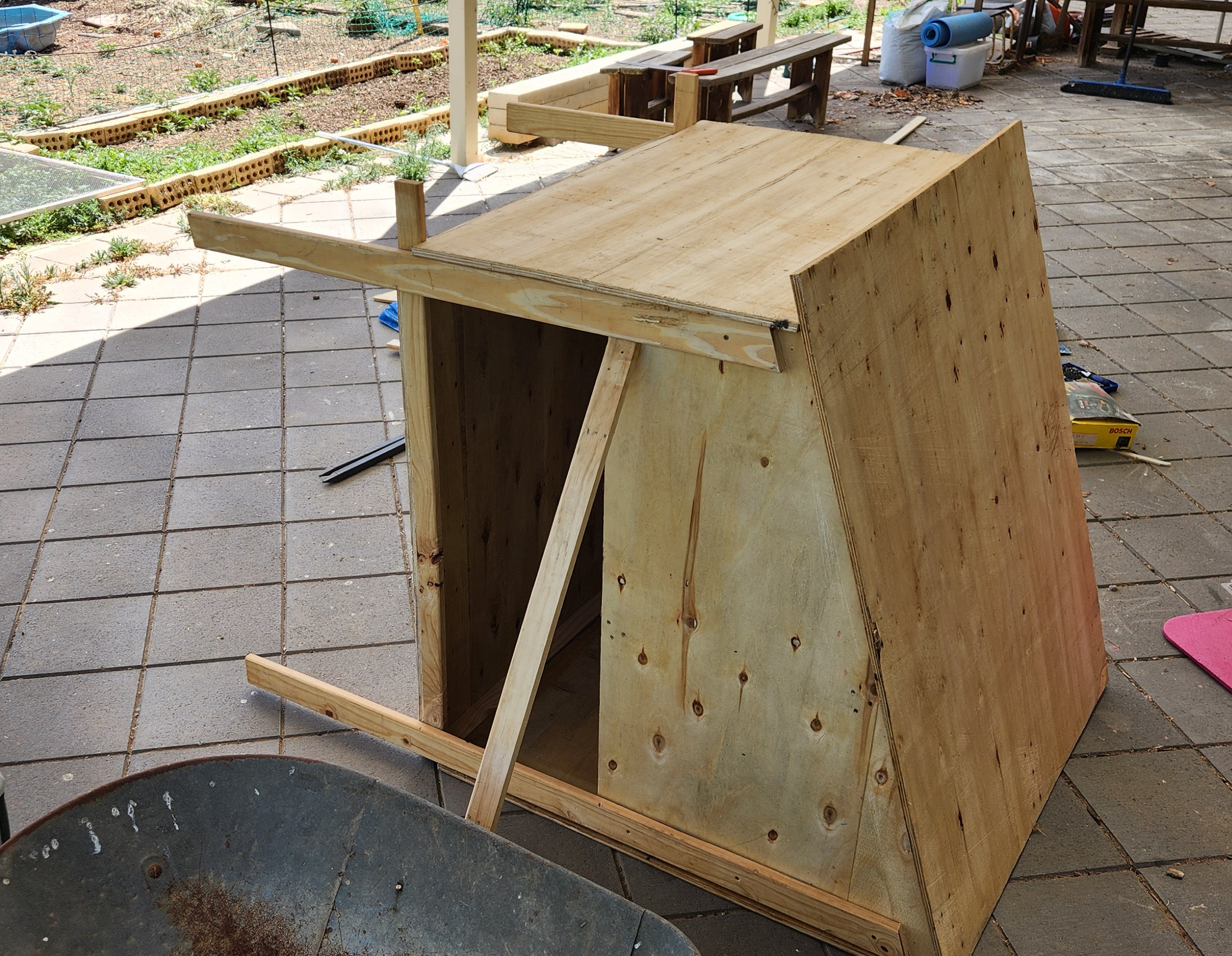
On 18 November 2024 I was able to complete the construction, less a couple of features, of the Super Chook House Mk 2.
The original Super Chook House had been purchased online sometime in 2018. I don’t recall all the details, but it came flat packed and in all probability been make somewhere oversees. It was made in a light wood, probably western red cedar, and looked like a small cottage including a chimney. It still needed to be painted, which caused a two year delay, given all the other things going on, before it was able to host our first flock. (More details in in the link above.)
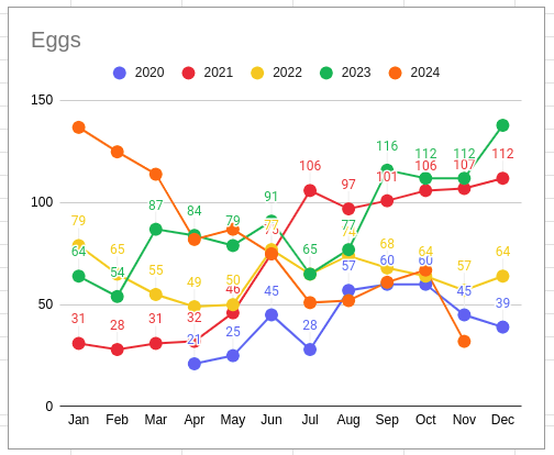
Egg Production – Apr 2020 – Nov 2024
Egg production began in April 2020.
The chickens have been a great edition to the family and have been both a great source of eggs and entertainment. They have somehow managed to avoid “sanctions” as one needs to be ever vigilant, as the little dinosaurs will, without hesitation, exploit any gaps in the fencing to raid unprotected vegetables in the garden. It is a fair trade.
It has been four and a half years, and the painting didn’t really work everywhere. The roof had rotted out on one edge, but it all came to a head when the floor fell out. A new chicken coop was required. The Super Chook House Mk2 project was hatched but was there a alternative, a better option, to the previous version? I don’t know how long it would take to fix, but I don’t think the chickens would be able to cope with another two year delay. I’m sure they would, after all they’re chickens, but it certainly wouldn’t be the best solution, and this was an opportunity to try something different.
There were parts of the original coop that could be reused. The original kit came with an enclosed cage, which was meant to be bolted onto the side. Due to the painting, which was never completed for this part, this feature never got added. Instead, the mesh panels ended up being used for vegetable protection technology, protecting them from the chooks and other raiding avians. I’m looking at you, blackbirds!
Other reusable parts included: the large metal tray in the base of the coop (although this has been found to have rusted through, so an alternative is required); the nesting boxes, with their own tray inserts; the ramps into the coop; and the roosting rails.
The Design
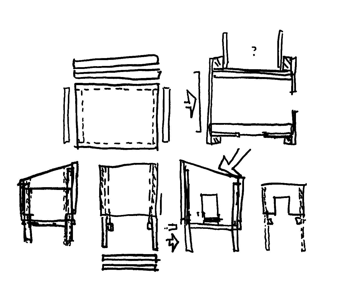
Rough Design
A local council curbside rubbish collection was booked, so the clock was now ticking. Two months to go.
Design work began, on and off, in the evenings in front of the TV (old school).
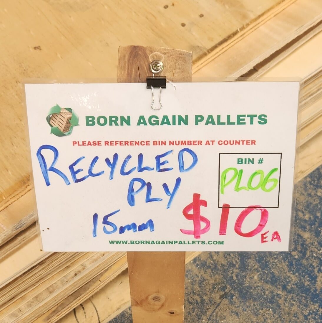
The plan was always to try and make use of recycled wood fromBorn Again Pallets. This Adelaide business breaks up and sells the materials from wooden pallets (it’s in the name) but I have also seen this material used in other community projects (Video: Microbat Nesting Box Workshop). Bunnings had blog posts of similar chicken coop projects using recycled timber (Chicken Coop, Nesting Boxes). I won’t pretend that I have the skill of these master wood workers, but I have a jigsaw, so how hard can it be? I don’t think I will need the router for this project.
The design went through several iterations. where the plan was to provide a chicken coop similar to what I had (size, features) but made as simply and easy as possible, made out of material which would hopefully last a little bit longer.
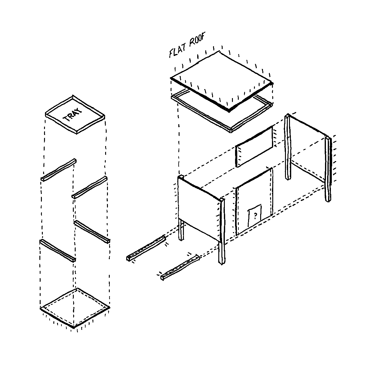
Isometric Construction View
In the end, the plan needed 6 sheets of plywood, for the sides, floor and roof, 4 posts for the legs, and additional batterns for edging the floor tray and the roof. The size was based around the existing metal floor tray, with other measurements taken from the existing coop. Leg height (500mm), Nesting Box height (350mm) and Doors (350x300mm). The height was taken as the maximum size allowed by the plywood sheets, and the roof pitch was chosen to be about 30 degrees.
The calculation of the maximum possible roof angle, given the size of a plywood sheet, was outsourced to the family’s year 11 student, who made use of their trigonometry knowledge to confirm that this was possible.
Part of the larger plan is to also mount a solar panel on the roof to power some sensors etc. so the the coop was to be orientated with the slope of the roof facing north.
Getting the wood
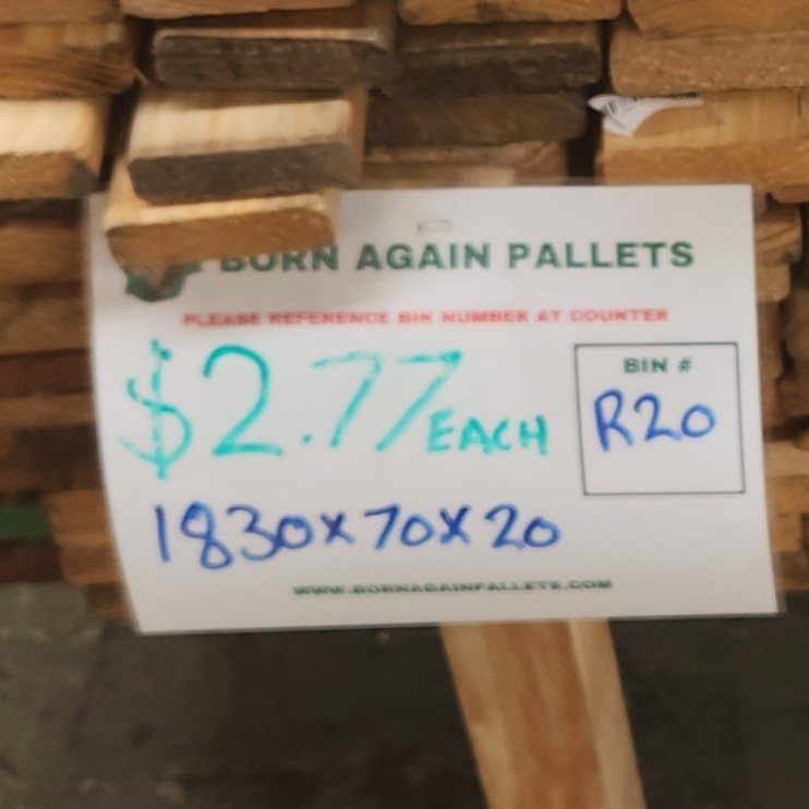
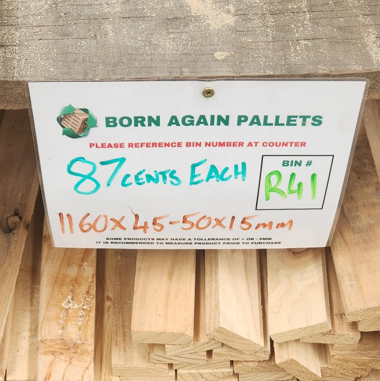
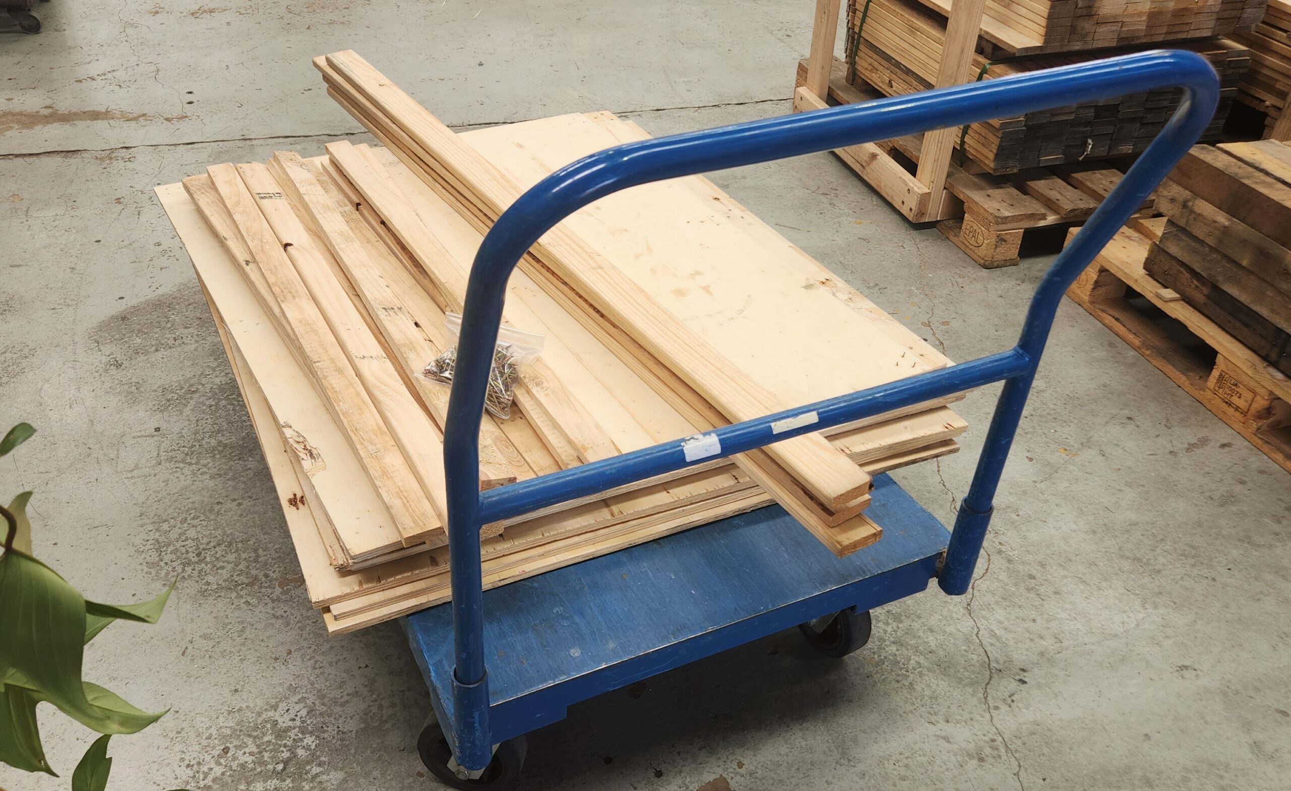
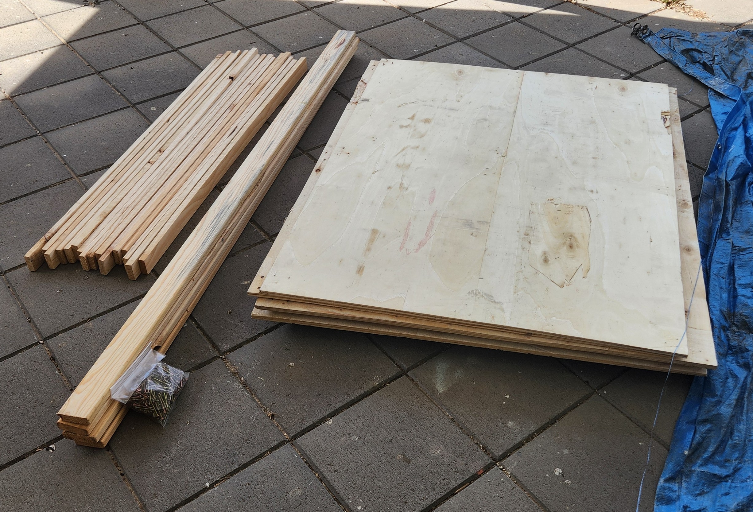
With a design in mind, it was off to Born Again Pallets so see what material they had. Time had also run out. This shopping trip was on a Friday, and the Council rubbish collection was booked for the next Tuesday, so everything was going to be done have to be done in one weekend.
It was a successful trip. Even though some compromises were made, all the required materials were purchased, including a packet of screws.
A trip to Bunnings was also made to pickup some timber oil, which was applied to the plywood. It was hoped that this will allow the wood to last a little bit longer and it also included some anti-bacterial properties. We will see how this goes.
Construction
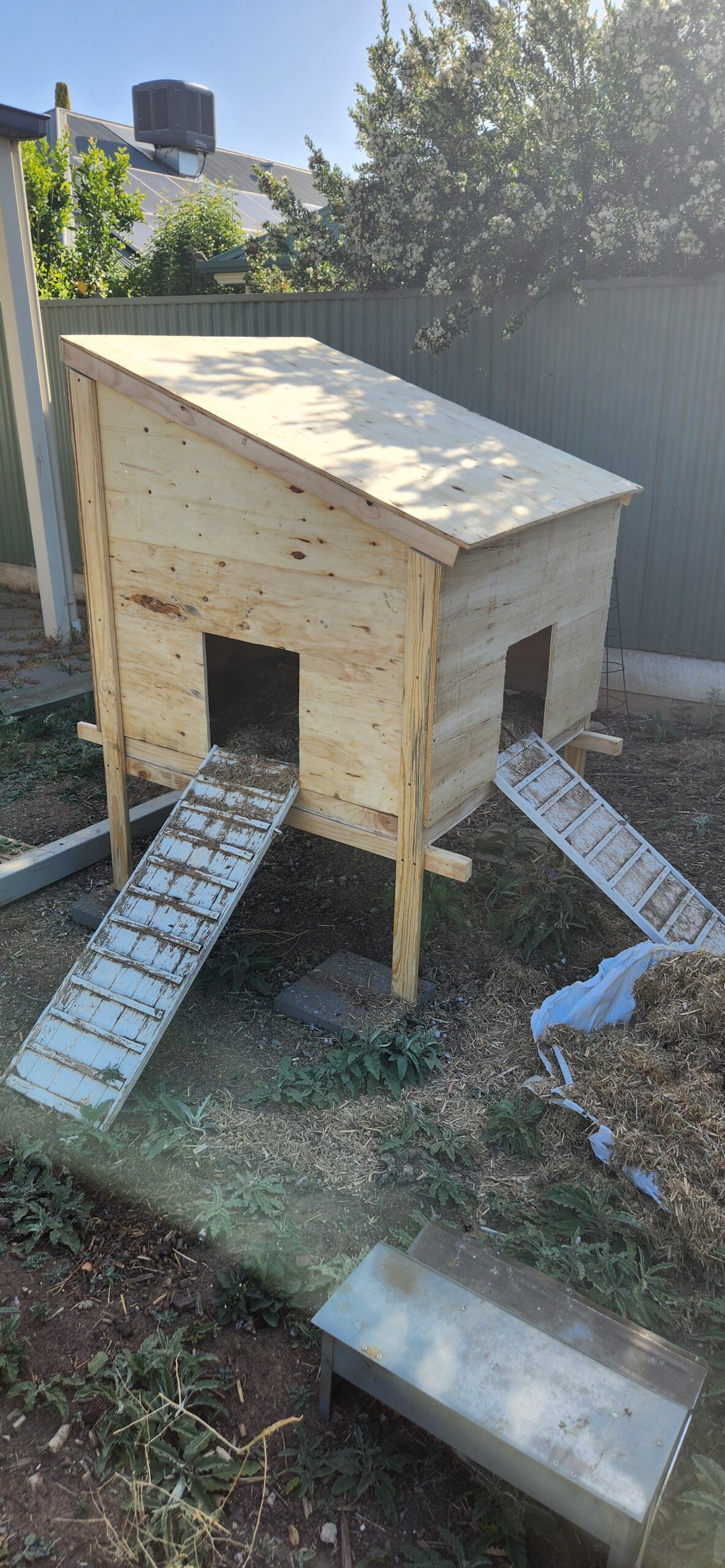
So, over a couple of intense days, and with some help from some interstate visitors (thank you Tim!), the new coop was constructed.
The completed Coop
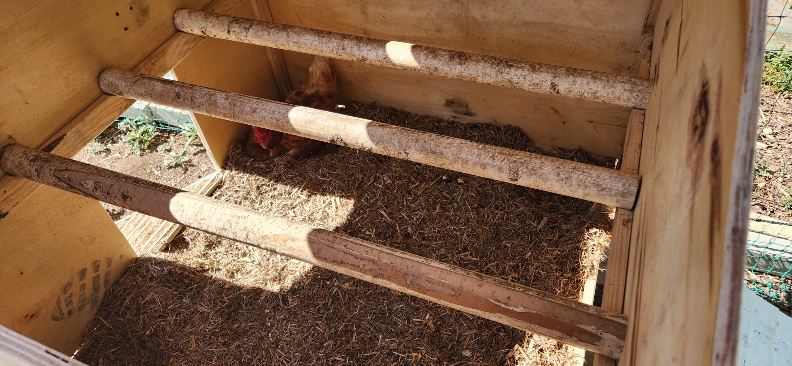
It was very much a fit as you go type of project. As mentioned, the design was based around the size of the metal tray floor of the previous coop. A drawer for this was constructed, and then the walls and roof were then added to fit around this. Pieces were tacked together to confirm the fit, before completely fixing everything in place. The previous roosting rails were also mounted inside.
It has all come together, a lot better than I had hoped.
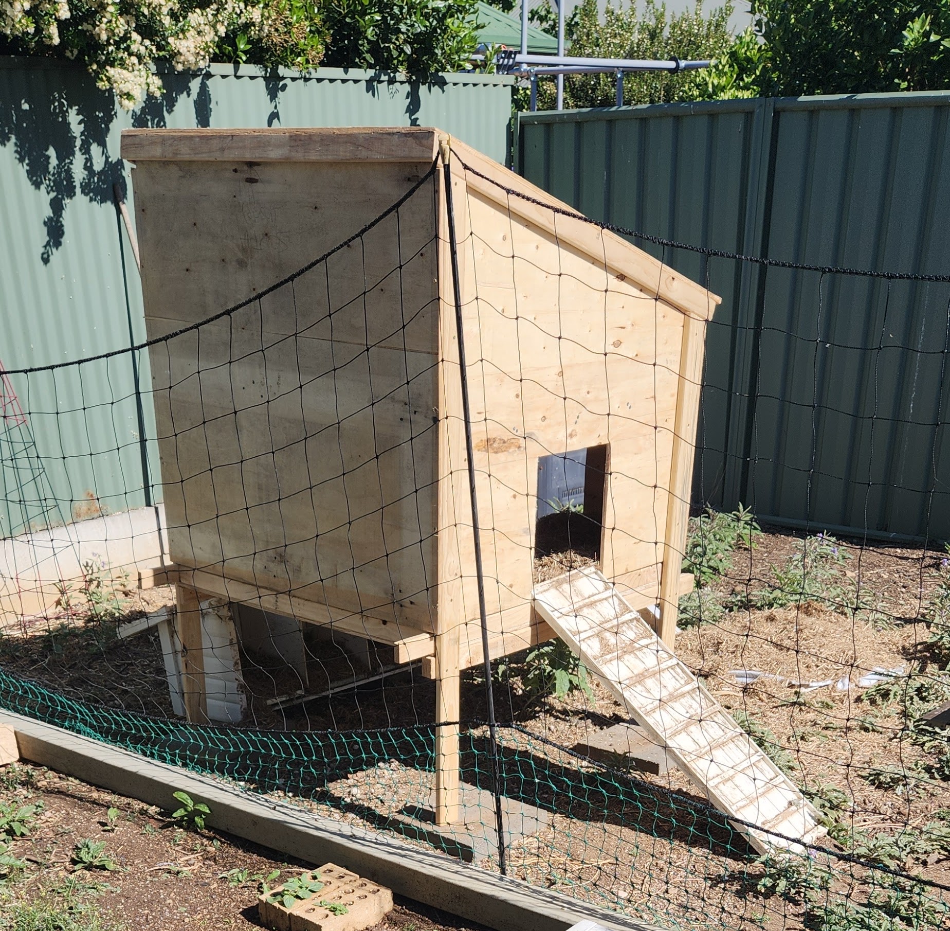
So, in the evening before the council curbside pickup, the old coop was hauled out to the curb. It was replaced with the new one, reusing the existing ramps, and with some sugercane mulch was all ready for use.
Some Final Comments
The design was found to be fairly robust. The long freehand jigsaw cuts, which didn’t make for the straightest of edges, didn’t compromise the final outcome. The floor slides easily out for cleaning, and the coop is now also accessible from the top as the roof lifts off.
The old nesting boxes still need to be attached to the side (using the original bolts). If more access is required, an access panel could be added to the large wall.
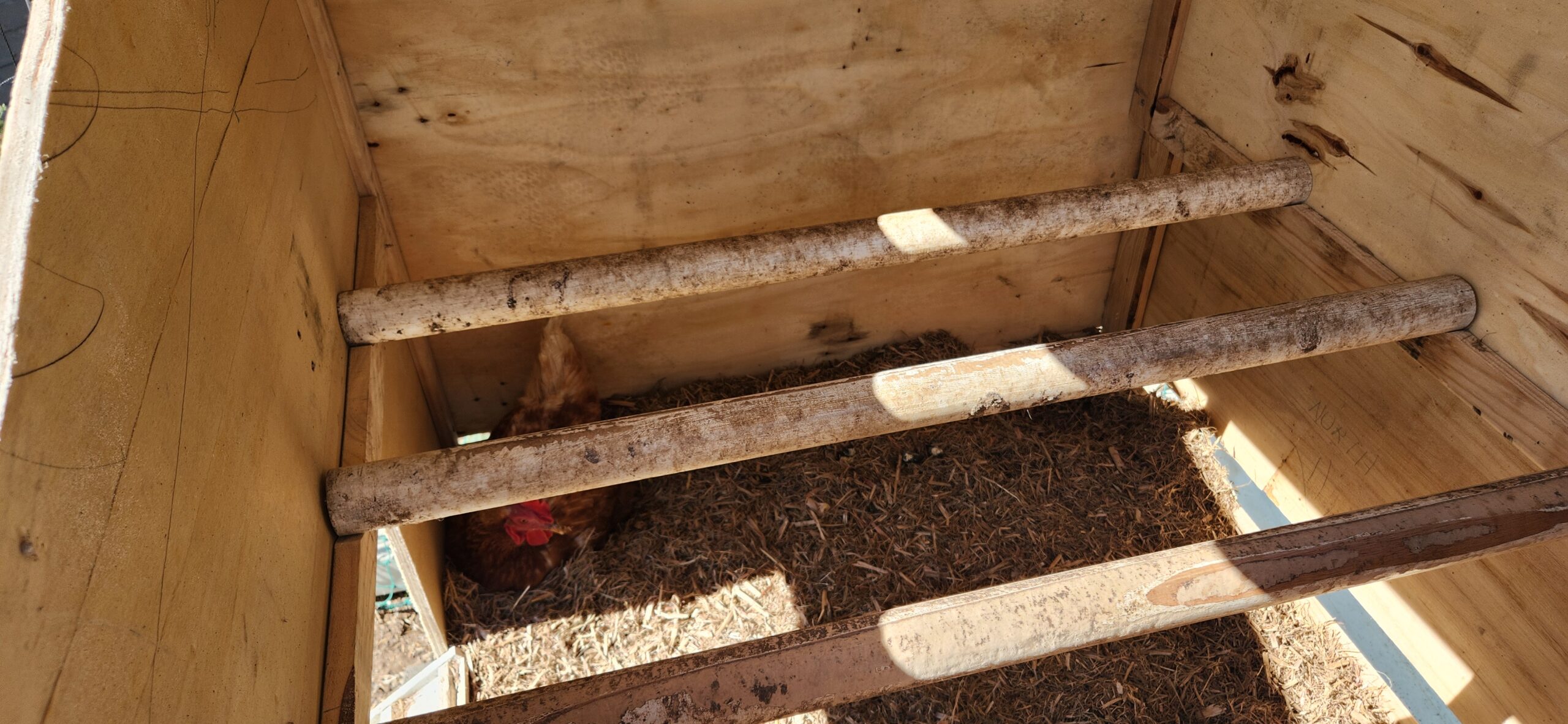
The chickens appeared to have enjoyed their first night in the new digs. I didn’t hear any complaints. See the images below, where ‘Pants’ is making use of the new facilities.
This post is about how setup Home Assistent to gain a greater understanding of how you use the energy in your home. These instruction are for if you only have is a regular electricity meter, without having additional power monitoring installed. (Installing additonal power monitoring typically requires the services and costs of an electrician.) It is possible to manually record your daily power usage from your meter and enter it into Home Assistant.
NOTE: It is possible to use just an ‘input_number’ to get the data and display it on the screen in Home Assistant, and display it in graphs etc. Unfortunately, this data is only currently maintained for 10 days and is then dropped. Using a ‘sensor’ template will treat this data like a regular sensor.
Also
If automated monitoring is available later then this setup can be used to give you even more insight (with minimal changes);
Individual device monitoring can be added though the use of relatively inexpensive ‘Smart Plugs’ which both allow remote switching control of appliances, and individual appliance energy monitoring.
The following instructions assume that you have an operational ‘Home Assistant’ system (it is very easy to obtain, install and configure if you don’t), and are able to make use of the ‘Energy’ dashboard. Some familiarity with Home Assistant is also assumed. (Home Assistant is availble as a downloadeble system image for the RaspberryPi, as well as fully installed system in the Home Assistant Green).
Note: As this meter reading process is a manual version workaround of an eventual automated system, the time of the input of the reading into Home Assistant is taken as the time of the meter value. This needs to be kept in mind, as this timestamp is used to calculate daily usage etc. so it isn’t possible to record a set of readings and then input them at a later date. It is best to enter them into Home Assistant as soon as possible.
Daily Meter Readings
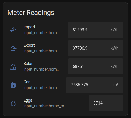
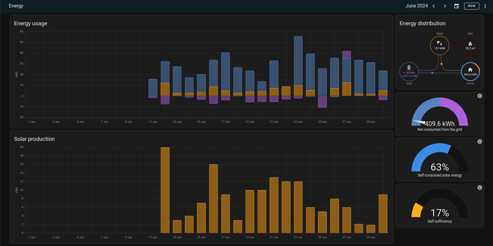
While Home Assistant is designed to be used with an automated meter reading system, it is still possible to get data and make useful observation with daily meter readings. The following describes how to set this up. The final result will be a meter reading dashboard with data entry fields, and a energy dashboard that can display the energy usage of the household over an extended period, say a month or a quarter.
The process is then:
Manual meter reading
  --> Data entry into Home Assistant
  --> Display household energy usage.
The example installation that this article uses is a household with a bi-directional electricity meter (records and displays power import and export separately), with solar panels and an inverter with an energy production meter.All of these are displayed in kWh.
It is possible to use the same method to add addition meter readings, and the example shows that this has also been done to record the gas meter reading and daily egg production.
Note: Using the ‘total’ meter reading, rather than a ‘daily’ value, ensures that possible errors caused by the meter reading process are minimised. Any error in a reading will be ‘fixed’ by a correct subsequent reading.
These instructions are for Home Assistant– 2024.7.1. As Home Assistant is under active development, this may change.
Getting Started
Home Assistant will need several entitles configured for each meter being recorded.
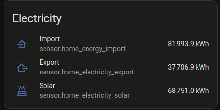
The first meter that we will consider is for electricity from the grid, which we will call “home_electricity_import”. Additional meters to consider will be “home_electricity_export” (excess energy sent back to the grid), “home_electricity_solar” (energy produced by the PV system), “home_gas_import” (gas meter readings) and “home_product_eggs” (how productive have my chickens been) and are added in exactly the same way.
We create an ‘input_number’ entity for recording the meter reading, and then create a ‘sensor’ entiry (via a helper/template) which makes the reading available to the rest of the system as a sensor.
Add a ‘input_number’ entity
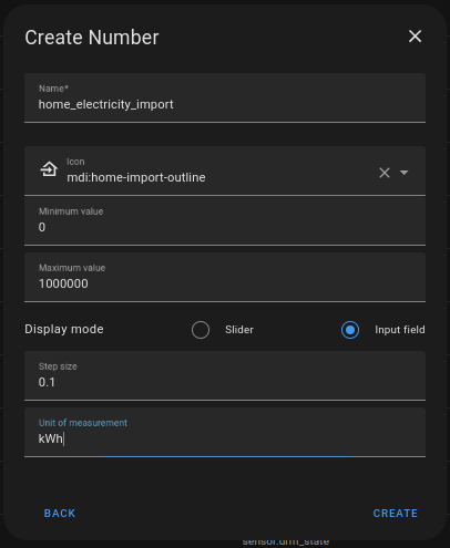
Create an ‘input_number’ entity for entering the meter reading with the following. From:
Settings
  -> Devices and Services
  -> Helpers (top menu)
  -> CREATE HELPER
  -> Number
then press ‘Create’
The entity that is created has the full name of “input_number.home_electricity_import”.
After the entity has been created, the details can be edited by selecting from the entity screen in “Devices and Services” and clicking on the ‘configuration’ (cog) button.
In addition to the above parameters, this screen allows you to allocate the entity to an Area, or allow integration with voice assistants, amongst other things.
The meter reading can updated in Home Assistant by entering the new value in the field displayed when the entity is selected. The time of the input is used as the time of the reading.
(Setting up a dashboard to allow data entry will be described shortly.)
Add a ‘sensor’ entity based on the meter reading
We now need to create an entity with uses the value from the meter reading, and can be used in the Energy dashboard.
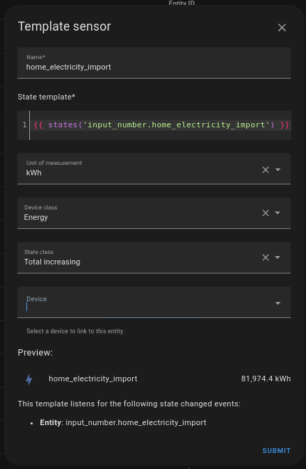
Similarly to the last step, we wantot create a ‘templete’ sensor from the helper menu.
Settings -> Devices and Services -> Helpers (top menu) -> CREATE HELPER -> Template -> Template a sensor
then press ‘Submit’
The entity that is create has the full name of “sensor:home_electricity_import” and should have automatically picked up the value of the meter reading.
The icon for the entity is automatically picked up from the ‘device class’ but can be changed in the entities ‘configuration’ screen.
Add entities to a dashboard
Before we attempt to setup the built-in Energy dashboard, we can check that everything is working as expected by usung two entity cards, one to display the ‘input_number’ and one to display the associated ‘sensor’ entity that we have just created.
input_number.home_electricity_import
sensor.home_electricity_import
Note: The card for the ‘input_number’ should display a data entry field, where you can enter the current meter reading. When you do this, the ‘sensor’ card should automatically change to reflect the new value entered.
Repeat for more meter readings
In the previous setup, whereever ‘home_electricity_import’ is used, replace this with the name of new meter to be configured, and repeat the steps.
Energy Dashboard
With the meter readings now being recorded, it is possible to import the data into the Energy Dashboard.
To configure
Menu: Energy
  -> … (top right menu)
  -> Energy Configuration
Then
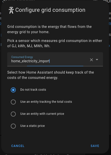
Electricity grid -> ADD CONSUMPTION
then press ‘Save’
Note: It is possible to create entities to track the existing energy price “home_energy_import_price” in AUD/kWh. This is left as an exercise for the reader.
If the other meter reading entities have been created, then they can also be added in a similar way,
Electricity grid -> ADD RETURN
Solar panels -> ADD SOLAR PRODUCTION
Gas consumption -> ADD GAS SOURCE
Note: The gas meter reading for my meter measures the gas in m^3. The bill is charged by kJ. Your gas bill should show the factor that is used by the gas company to make the conversion from volume (m^3) to energy (kJ).
The energy dashboard should now start recording your energy usage. It will take a while (possibly up to an hour) to register a new meter reading each day, but after a while you will now be able to see you energy usage and generation broken down by day, month etc.
Note: There is nothing stopping you recording meter reading more often than daily. It may be interesting and worthwhile doing a day of hourly readings to determine where the daily peak periods are.
Energy use of individual appliances
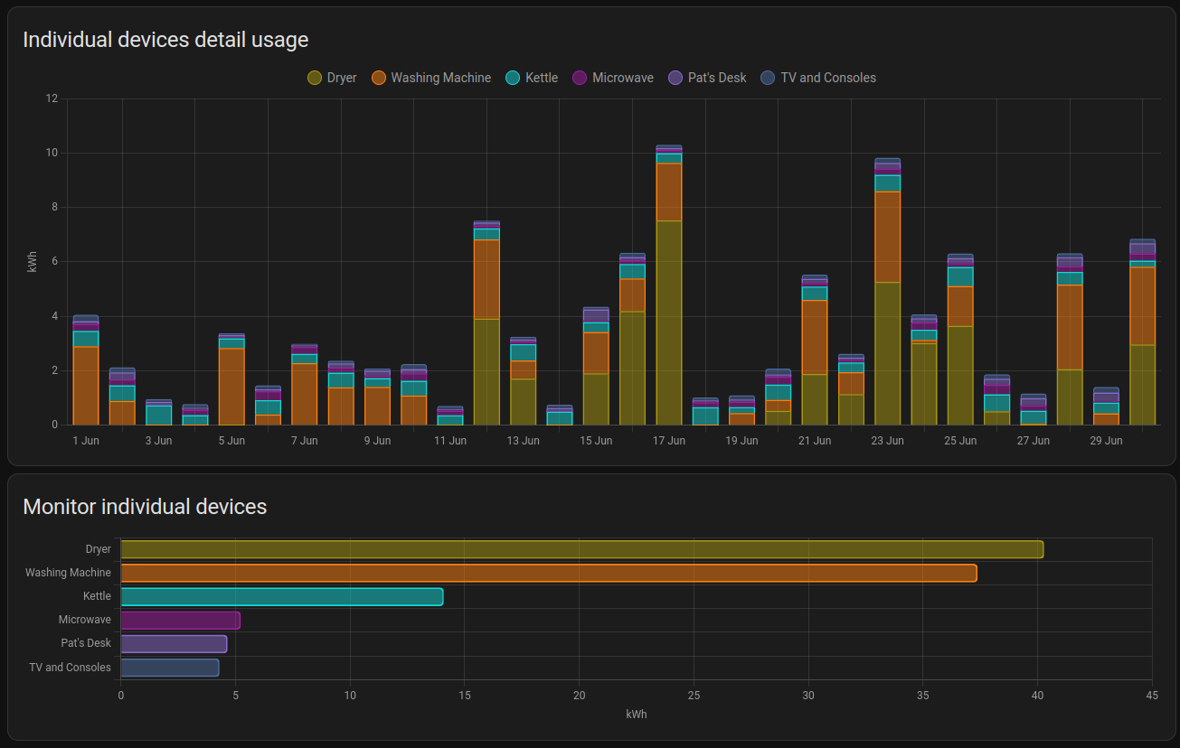
The energy dashboard also allows monitoring data for individual devices to be added to the display. I use the Athom Smart Switch v2 ESPHome (there is also a new version based on the ESP32-C3). These Smart Plugs, once connected to your Wifi network, are automatically detected by Home Assistant what can then monitor and control these devices.
Automating the Manual Meter Reading
It the reading of the meter can be automated and fed into Home Assistant then manual meter reading will no longer be required, and the reading can also be done much more often.
Once the data is being read into Home Assistant, via a meter reading sensor entity, the template sensor we created can be modified to use this new sensor instead of the ‘input_number’ entity.
Note: Some finessing may be required to match the new meter reading with the old ones eg. by adding or subtracting a fixed ‘offset’ amount.
Digression (and Rant) about Automated Meter Reading in Australia
<rant>
For many of the electricity smart meters around the world, there are Home Assistant integrations which allow their data to be read automatically, possibly as often as every 10 seconds. These were originally designed for in-home energy displays, and some countries even mandated a standard for this (eg. the P1 port on the Netherlands)
In Australia, unfortunately, the smart meters that are being installed in the National Electricity Market(NEM) do not come with this feature. For electricity customers, AEMO (the market operator) is relying on the Energy Retails to supply this information to their customers, but this customer data is typically only made available the next day after the ‘market settles’ (typically 24 hours later).
One solution is for individuals to install their own energy monitoring meter, inline and behind their electricity providers meter. This allows a home owner to capture the data that they need, but comes with its own issues.
the installation requires an electrician;
the meter readings may not agree with the existing meter, and would not be accepted by the energy supplier in a dispute;
it isn’t (easily) possible this way to take the monitoing wigh tyou if you move house;
it would a difficult option for a rental tenant;
it adds another point of failure into the home network
In Australia there is also a commercial market with product lines dedicated to providing this missing functionality. A lot of these products also put your data into the cloud, which can then be used by the collecing service to sell to other businesses.
Your power usage should be made available to you as you use it, and not 24 hours after the event, and this should be available to all consumers by default.
All electricity customers are currently paying for smart meters in their electricity bills as there is a smart meter allowance included in the “default market offer” (DMO) which is used by the energy retailers for creating that energy plans on th eNEM.
Changing this for consumers does not appear to be a priority for anyone involved in the industry.
</rant>
Update: It appears as though there are particular models of Smart Meter being used in Victoria that has a Zigbee based “In Home Display” that can provide this functionality.
At the recent Everything Open Conference, I attended a taik by Vic OIiver on the one handed keyboard called the Quirkey.
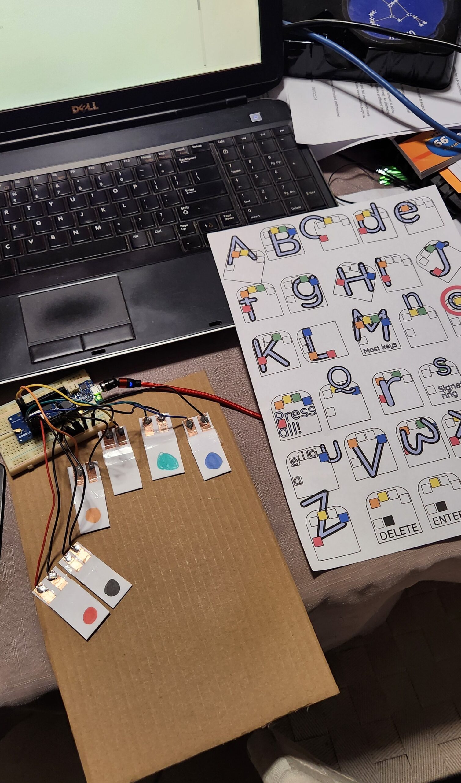
I am attempting to write this blog post using a version of this keyboard I have made out of cardboard, a Arduino MKR 1310 board and some other bits and pieces of stuff that I found lying around the house. (I am going to have to stop here and go back to my regular QWERTY keyboard. I will have another practice later, but at the moment I am finding that I am using the ‘backspace’ more than I would like to.)
While looking into the Arduino code, it occured to me that I had a dev board that would actually work with this code (the Arduino MKR 1310 which had been used in a previous project). In particular, this board supported the HID, and Keyboard and Mouse libraries, which is what allowed this board to appear as (surprise, surprise) a keyboard and mouse device when plugged into a USB port. There ae many naferious project ideas for this sort of technology, but I don’t think that the usefulness has been explored enough.
The Design
This project code takes the corded (multiple symaltanious keypress) inputs, of six buttons, and converts it into regular keyboard input. Vik’s presentation gives more of the backgound, and reasons why knowing how to use one handed keyboard is a good skill to have. In addition, the documentation includes helpful tools to assist in learning this skill, as will as a typing tutor.
So… I have an Arduno board that will do the job (there is a good list of supported boards on the HID Library page), I just need to get some switches.
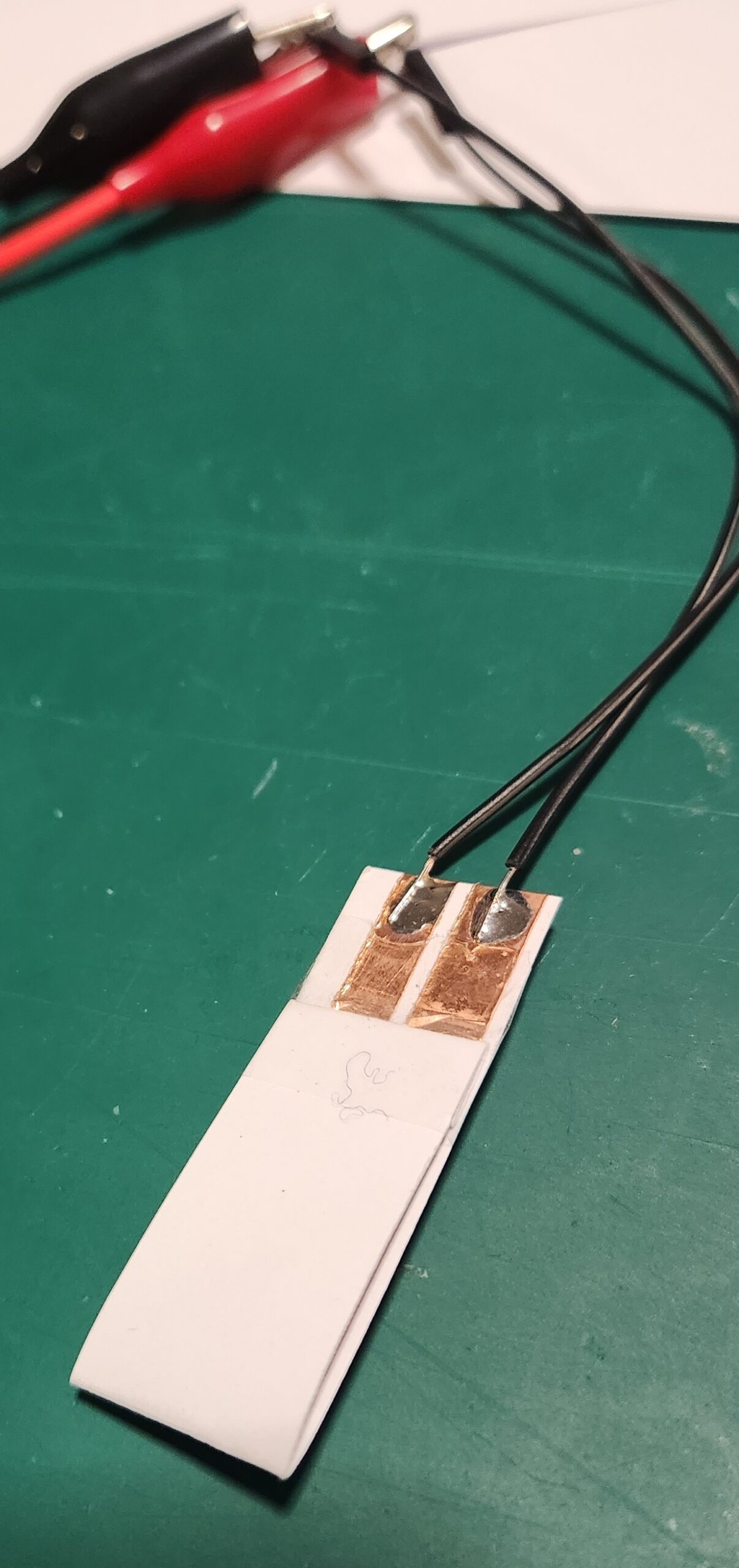
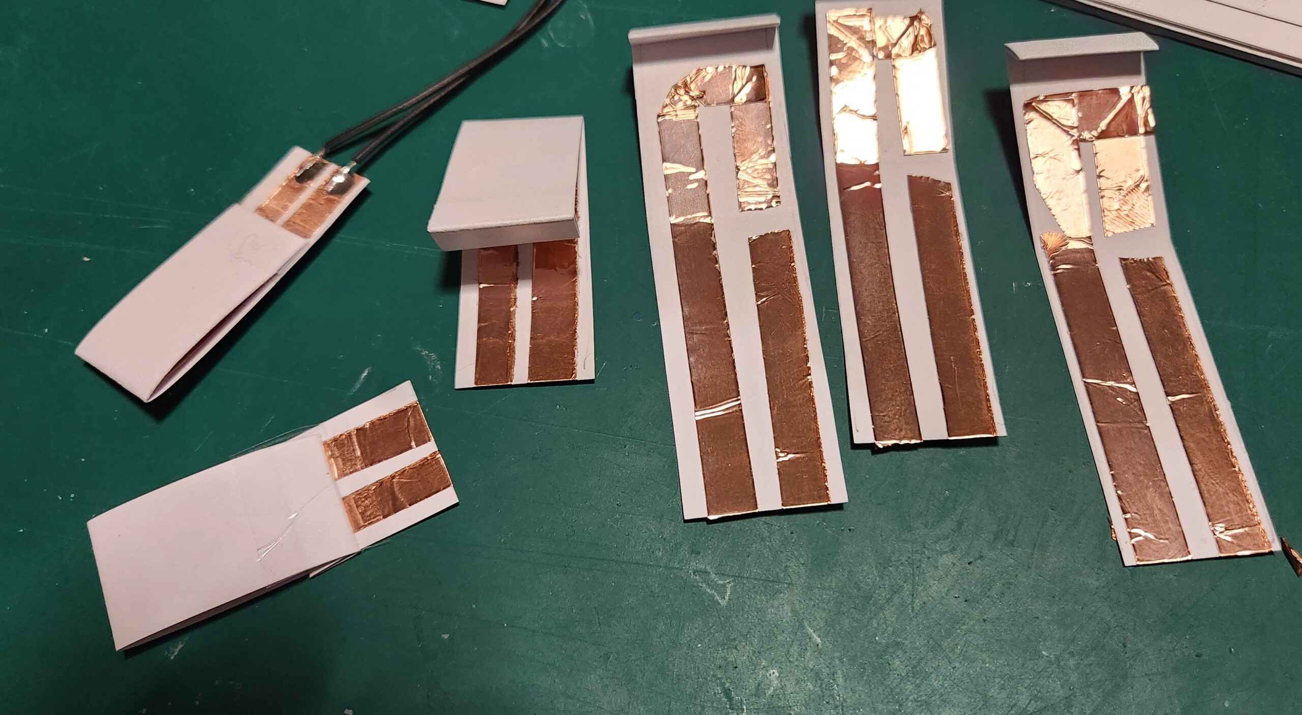
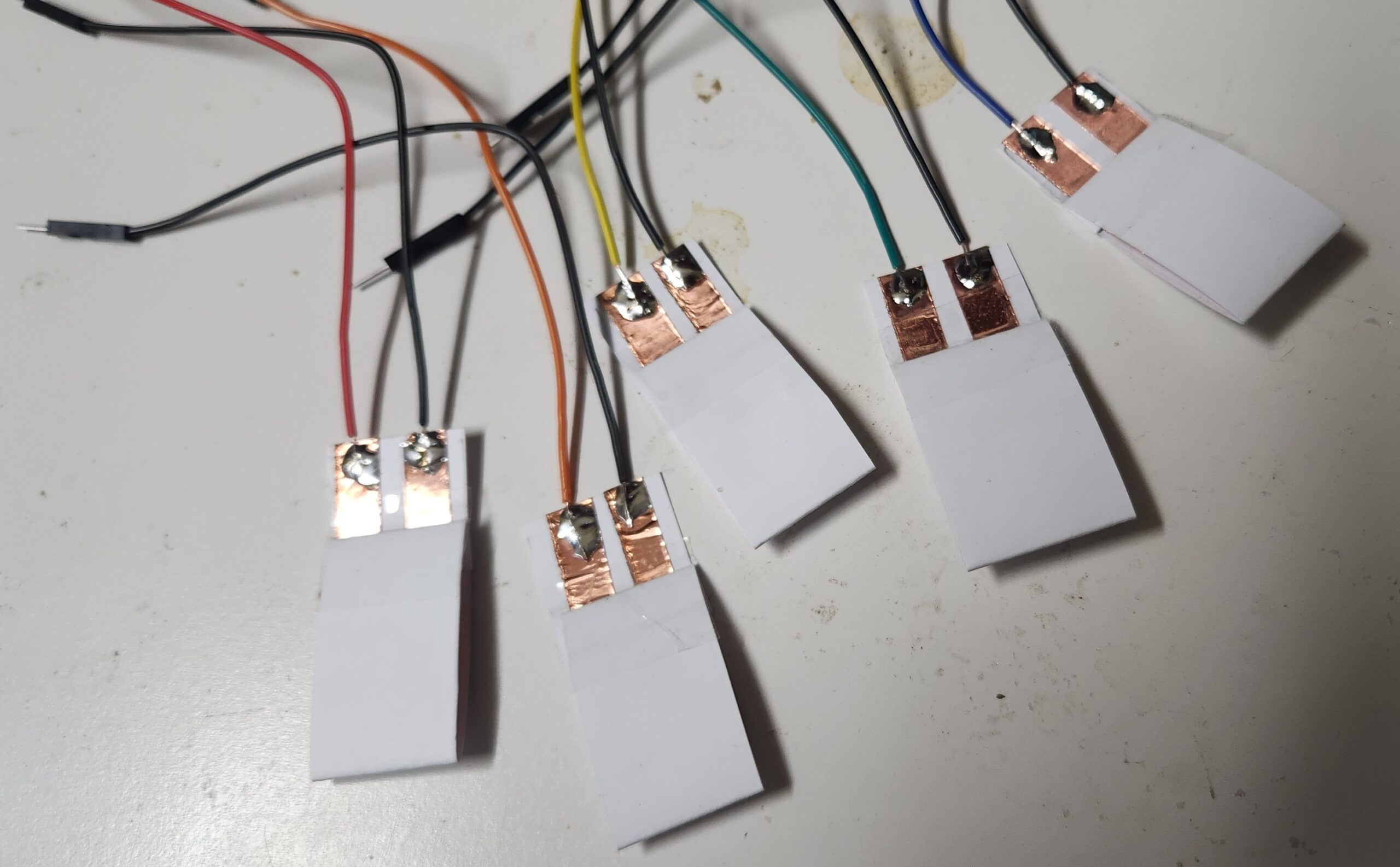
The latest version of the Quirkey keyboards were the result of lots of trial and erro experimentation, and consited of a 3D printed shell with six mechancal switches. My Prusa printer is currently broken and I didn’t have any unused mechanical switches within reach, but I did have some cardboard, copper tape and my trusty soldering iron. So, after some of my own experimentation, we get the following design…
The cardboard switches are stuck down onto a piece of cardboard, wired up to the Arduino MKR 1310 board (any MKR 1000 series boar will work), and programmed with the MicroWriter Ardunio sketch. (Comments in the sketch indicate which pins connect to which switch.)
There is a 5 second delay on startup, but the board is now detected as an “Arduino LLC Arduino MKR WAN 1310 Keyboard” and “Arduino LLC Arduino MKR WAN 1310 Mouse”, and works as advertsed.
Conclusion
This is a great cheap-n-cheerful project incorporating a bunch of useful ‘maker’ techniques (soldering, wiring and Ardunio programming) which can be completed resonably quckly.. and at the end you get something useful to play with.
The switches aren’t perfect, but it’s great to have something to use to learn the one handed keyboard technique.
After practicing for a while, for not much more, the paper and copper switches and cardboard can be replaced with something a little more permanent. (A project for the future.)
They have just launched the Open Home Foundation, which is a Non-profit Organisation, which will host the Home Assistant, ESPHome and related projects. This means that these projects can never be bought by another commertial company or orgaisation, and will always be free and open.
Nabu Casa will continue to support Home Assistant with its subscription service, which will fund continued development on the platform.
It was a most enjoyable time exploring topics covering Free and Open Source Software (FOSS) topics, including some of the social and inclusivity issues.
The videos of the conference will be made available at some stage.
The Everything Open 2025 Conference will be held in Adelaide, so watch out for the announcements (and subscribe to the Linux Australia mailing list).
This article is part 1.5 of the series – Developing a component for ESPHome, for the SX1262 LoRa Radio Chip. The process getting the LoRaWAN functionality of this development board to work with The Things Network proved to be an excercise infrustration management, so the following is a write up of what was required to get it to work. The following is my account of setting up the Heltec Wireless Lite V3 for connecting to the LoRaWAN network. There were several false starts, but in the end it was possible to send data and decode it correctly.
Development Environment
ArduinoIDE and the Heltec Board Manager extention
The Heltec boards are defined by the following file (link) which is added through the menu in Preferences…->Additional boards manager URLs
This file specifies that esptool 3.3.0 is used for writing the firmware to the Heltec board. There is as issue with usung this version for the Heltec V3 boards, in that the firmware compiles and installs, but puts the ESP32-S3 processor into a boot loop.
Install the ‘SX126X-Arduino’ library with the library manager (currently version 2.4.0).
A small fix is required. Edit the ‘src/mac/Commissioning.h’ file and comment out the check for whether the LoRaWAN Region has already being set (Line 40).
Example Code – LoRaWAN.ino
From the LoRaWAN library, the LoRaWAN example was copied and modified to get the system to work.
Modifications:
Copy the LoRaWAN.ino file, and remove other unnecessary files. Fix the source to remove the dependancies.
Simplify the code. eg. Remove the code sections used for other processors.
Set the authentication mode to OTAA, the device type and the Frequency bandplan region to AU915 by adding the optional parameters to ‘lmh_init() – true, CLASS_A and LORAMAC_REGION_AU915.
Ensure that the correct LoRaWAN sub-band is being used for AU915 by calling ‘lmh_setSubBandChannels(2)’.
Additional Serial.println() output added to trace the execution of the firmware, including the output of the LoRaWAN parameters.
The LoRaWAN parameters (AppEUI, DevEUI and AppKey) are set in the following section.
The Things Network
The Heltec V3 Devices have not been configured as known devices in The Things Network, and need to be specifically setup.
Select “Enter end device specifics manually”.
Add a new device and set the following Device Parameters
Frequency Plan: Australia 915-928 MHz, FSB 2 (used by TTN)
LoRaWAN Version: LoRaWAN Specification 1.0.2
Regional Parameters version: RP001 Regional Parameters 1.0.2 revision B
Create a JoinEUI (previously known as the AppEUI). This can be freely set any 8-byte value, but cannot be changed once set.
The other parameters that need to be set are:
DevEUI
AppKey
The easiest way to to get these values is to allow them to be automatically generated by The Things Network interface. They can be specifically set if the manufacturer of a device has preprogrammed a device with a LoRaWAN configuration.
Build and Install Firmware on Device
Update the definitions of the LoRaWAN parameters in the code to reflect the values just generated. It is possible to directly produce the desired strings (in ‘msb’ format) from The Things Network device interface.
It is also helpful to also have these values displayed when the board os booted.
The firmware compiles and can be installed onto the Heltec board. On boot, it should connect to the LoRaWAN network and start transmitting packets of data.
Uplink Payload Formatter
On The Things Network, to check that the uploaded data is correct, the following JavaScript payload filter can be installed for the device, which will decode the data and (hopefully) display the correct string.
function decodeUplink(input) {
var result;
result = String.fromCharCode.apply(null, input.bytes);
return {
  data: {
    bytes: input.bytes,
    result: result
  },
  warnings: [],
  errors: []
};
}
Notes, Issues and Errors
When selecting and playing around with different LoRaWAN Versions and Regonal Parameters, it appears as though The Things Network does not reset LoRaWAN values properly. Changing the LoRaWAN version to 1.1.0 required the additional parameter ‘NwsKey’. If the LoRaWAN version is then set back to 1.0.2, this value becomes the one that is used for the AppKey. There is a note about this in The Things Network interface, but it is not obvious what is required.
Care needs to be taken when setting the nodeDevEUI and nodeAppEUI not to set them the wrong way around. If connection packets are being received from the device, but it isn’t able to authenticate, then the nodeDevEUI will be correct, but the other parameters (including LoRaWAN Version) may be wrong.
If only intermittent transmitted packets are seen in The Things Network, and the device is not able to authenticate, check that the firmware has selected and is using the correct LoRaWAN sub-band.
Selecting other LoRaWAN versions eg. 1.1.0 will require additional parameters to be set., namely NwsKey. This setting is not removed if the LoRaWAN version is set back to 1.0.2, and this value is then used instead of the nodeAppKey. This is a trap. The only way to fix this is to delete the device definition in The Things Network and start over.
Next Steps
Convert the Arduino LoRaWAN firmware to ESPHome. This will allow LoRaWAN to be able to be used with the other ESPHome functions, including support for all of the existing supported sensors and outputs, and also operate with Home Assistant. (This will be Part 2 of the “Developing a component for ESPHome, for the SX1262 LoRa Radio Chip” series.)
Test with the Helium network. Register the device on the Helium network and check that data is routed correctly.
Implement as Class B and Class C LoRaWAN device. The example code currently only uploads data. Class B and Class C deviced allow data to be downloaded as well, for device control.